1 ethernet connectors, Figure 4-21: rj-45 ethernet connector, Table 4-22: lan pinouts – IEI Integration ECN-360A-HM65 User Manual
Page 58: Table 4-23: rj-45 ethernet connector leds
ECN-360A-HM65 Em b e d d e d S ys te m
P a g e 45
4.3.1 Eth e rn e t Co n n e c to rs
CN La b e l:
LAN1 a n d LAN2
CN Typ e :
RJ-45
CN Lo c a tio n :
CN P in o u ts :
The motherboard is equipped with two built-in RJ-45 Ethernet controllers. The controllers
can connect to the LAN through two RJ-45 LAN connectors. There are two LEDs on the
connector indicating the status of LAN. The pin assignments are listed in the following
table:
Pin
Description
Pin
Description
1
LAN1_MDI0+
7
LAN1_MDI2+
2
LAN1_MDI0-
8
LAN1_MDI2-
3.
LAN1_MDI1+
9
LAN1_MDI3+
4.
LAN1_MDI1-
10
LAN1_MDI3-
Table 4-22: LAN Pinouts
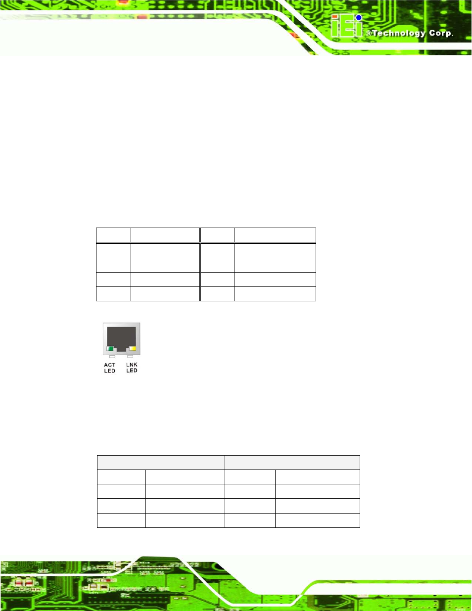
Figure 4-21: RJ-45 Ethernet Connector
The RJ-45 Ethernet connector has two status LEDs, one yellow (activity/link) and one
green/orange (speed). The yellow LED indicates activity/link on the port and the
green/orange LED indicates the connection speed. See Table 4-23.
ACT/LINK LED
SPEED LED
STATUS
DESCRIPTION
STATUS
DESCRIPTION
OFF
No Link
OFF
10 Mbps connection
YELLOW
Link
GREEN
100 Mbps connection
BLINKING
Data activity
ORANGE
1000 Mbps connection
Table 4-23: RJ-45 Ethernet Connector LEDs