10 cable connections, 3 power-on procedure, 1 installation checklist – IEI Integration ECW-281B-N270-WT v2.00 User Manual
Page 70
ECW-281B Embedded System
Page 54
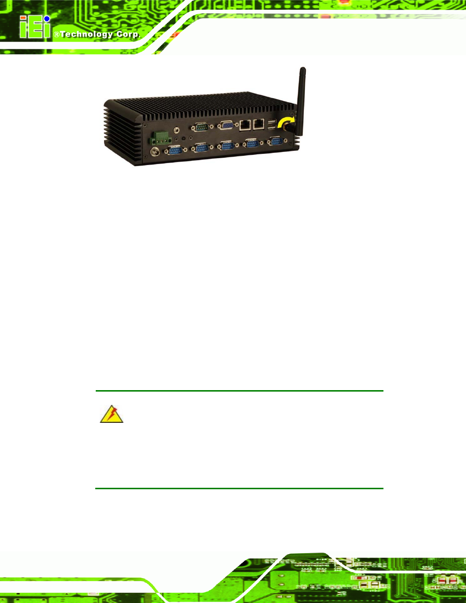
Figure 4-13: Wireless Antenna Installation
4.2.10 Cable Connections
Once the system has been mounted on the wall, the following connectors can be
connected to the system.
VGA cable connector
Serial port connectors
RJ-45
connectors
USB devices can be connected to the system.
The cable connection locations are shown in
768H768H768H
Figure 2-5.
4.3 Power-On Procedure
4.3.1 Installation Checklist
WARNING:
Make sure a power supply with the correct input voltage is being fed into
the system. Incorrect voltages applied to the system may cause damage to
the internal electronic components and may also cause injury to the user.
To power on the embedded system please make sure of the following:
The bottom surface panel is installed