2 serial port connector (com1) – IEI Integration ECW-281B-N270-WT v2.00 User Manual
Page 51
ECW-281B Embedded System
Page 35
The RJ-45 Ethernet connector has two status LEDs, one green and one yellow. The green
LED indicates activity on the port and the yellow LED indicates the port is linked. See
810H726H726H726H
Table 3-15.
STATUS
DESCRIPTION
STATUS
DESCRIPTION
GREEN Activity
YELLOW Linked
Table 3-15: RJ-45 Ethernet Connector LEDs
3.4.2 Serial Port Connector (COM1)
CN Label:
COM1
CN Type:
DB-9 connectors
CN Location:
See
811H727H727H727H
Figure 3-14
CN Pinouts:
See
812H728H728H728H
Table 3-16 and
813H729H729H729H
Figure 3-16
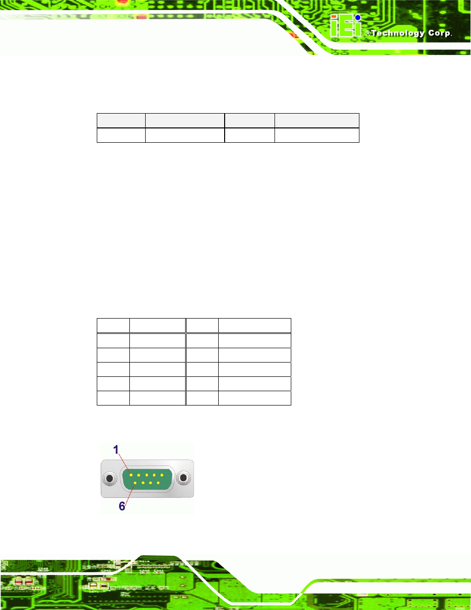
The 9-pin DB-9 serial port connectors are connected to RS-232 serial communications
devices.
PIN NO. DESCRIPTION PIN NO. DESCRIPTION
1 DCD
6 DSR
2 RX
7 RTS
3 TX
8 CTS
4 DTR
9 RI
5 GND
Table 3-16: RS-232 Serial Port (COM 1) Pinouts
Figure 3-16: COM1 Pinout Locations