WEATHER GUARD 1225 User Manual
Page 4
4
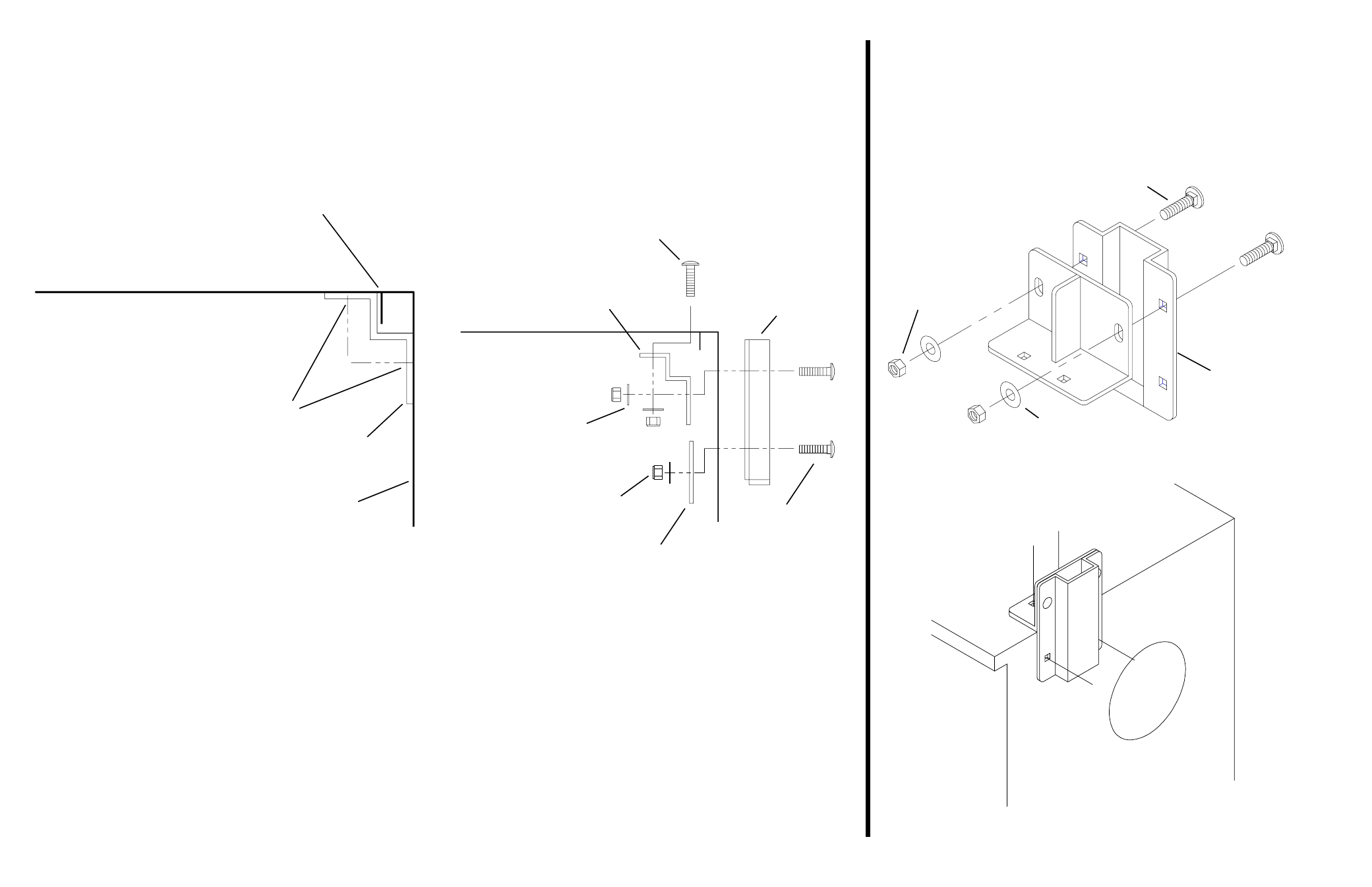
Figure 8. Assembled Leg Support - used for marking all rear mounting holes
Option 1 Installation -
Place a Lower Bracket at the top of the rear end
panel inside the service body, and in position side to side. Mark the centers of the
four obround holes (see Figure 5.). Remove the Lower Bracket, and using a
square, draw a line down 6 from the centers of the marks on the rear panel. Mea-
sure down 3-3/4 from the rear panel marks, and mark the lines. Drill the six marks
with a 7/32 drill bit. Re-drill the rear panel holes with a 7/16 drill bit. Re-drill the
top holes with a 1/2 drill bit. Repeat this procedure at the other side of the service
body. Loosely assemble a Leg Support, Lower Bracket and a Mounting Plate at
each rear location (see Figure 6.).
Leg Support
3/8-16 x 1-1/2
Carriage Bolt
3/8 Flat
Washer
Figure 7. Leg Support/Upper Bracket Assembly for marking at rear
Figure 5. Lower Bracket - used for marking
service body top and rear end panel
Seam/Flange
Knaphiede®
Service Body
only
NOTE: Use caution when
drilling so as not to thrust
the drill bit into the cab of
the vehicle.
Mark these holes
Service
Body
Rear
Figure 6. Option 1 Assembly
3/8-16 x 1-1/2
Carriage Bolt
(6 places)
Leg Support
3/8-16 Nylon
Lock Nut
(6 places)
3/8 Flat
Washer
(6 places)
Mounting
Plate
Lower
Bracket
long leg of
Lower Bracket
tap this Carriage Bolt
into the 1/2 drilled hole
Option 2 Installation (used only at the rear of the vehicle) -
Fasten together one Leg Support and one Upper Bracket (see Figure 7.). Place
the assembled Leg Support at the top of the end panel outside the service body,
and in position side to side. Mark the two square holes of the Leg Support and the
two of the Upper Bracket (see Figure 8.). Drill the marks with a 7/32 drill bit. Re-
drill the back panel holes with a 7/16 drill bit. Re-drill the top holes with a 1/2 drill
bit. Repeat this procedure at the rear on the other side of the service body.
Loosely assemble a Leg Support, Upper and Lower Bracket at each rear location
(see Figure 9.).
3/8-16 Nylon
Lock Nut