Roll follower adjust input (optional), Remote mode selector switch (optional) – Warner Electric TCS-200-1H User Manual
Page 9
9
Warner Electric • 800-825-9050
P-2003-2 • 819-0420
o 5. Connect the red wire from the high resistance
end of the remote potentiometer to terminal 7 of
terminal block TB1 of the TCS-200-1. Secure the
terminal screw.
o 6. Connect the shield lead from the cable to
terminal 11 of terminal block TB1 of the
TCS-200-1. Secure the terminal screw.
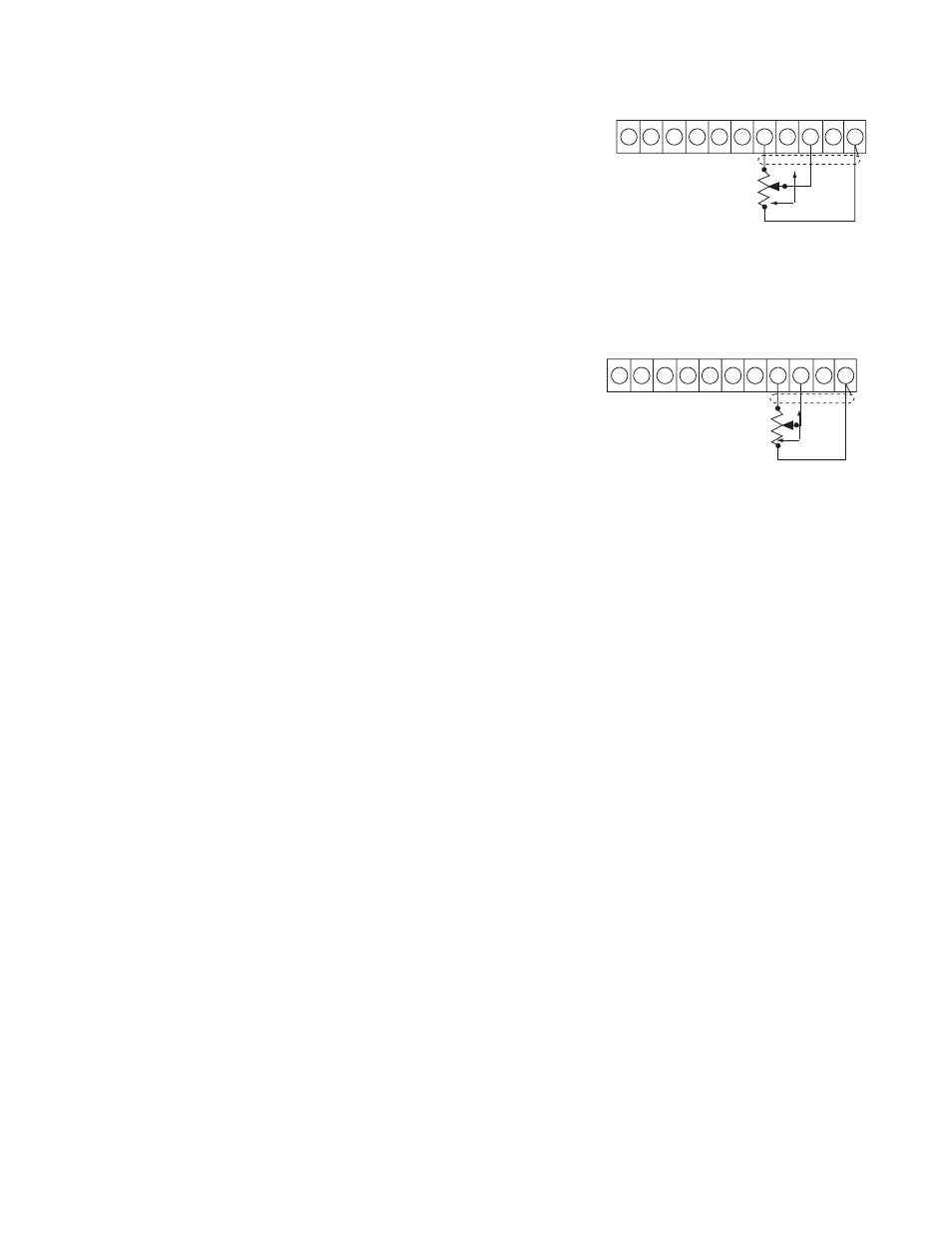
Roll Follower Adjust Input (Optional)
Refer to Figure 4b for roll follower adjust input
connections.
o 1. Wire a three conductor shielded cable to the
roll follower potentiometer previously installed.
Note: Using a shielded cable with wire colors red,
black, and green is recommended to simplify
potentiometer and terminal connections:
a. Black wire to low resistance end terminal of
potentiometer.
b. Red wire to high resistance end terminal of
potentiometer.
c. Green wire to wiper terminal of potentiometer.
o 2. Route the cable from the sensor potentiometer
to the control, keeping the cable segregated from
high voltage AC Power lines and other wiring that
may cause noise transients.
o 3. Connect the black wire from the low
resistance end of the roll follower potentiometer
to terminal 11 of terminal block TB1 of the
TCS-200-1. Do not tighten the terminal screw.
Snug down only.
o 4. Connect the green wire from the wiper of the
roll follower potentiometer to terminal 9 of
terminal block TB1 of the TCS-200-1. Secure the
terminal screw.
o 5. Connect the red wire from the high resistance
end of the roll follower potentiometer to terminal
8 of terminal block TB1 of the TCS200-1. Secure
the terminal screw.
o 6. Connect the shield lead from the cable to
terminal 11 of terminal block TB1 on the
TCS-200-1. Secure the terminal screw.
Remote Mode Selector Switch (Optional)
Refer to Figure 5a for the remote mode selector
switch connections.
o 1. Install selector switch at a convenient location.
o 2. Wire a three conductor shielded cable to the
external mode selector switch.
Note: It is recommended that a shielded cable with
wire colors of red, black, and green be used as this
will simplify switch and terminal connections.
a. Black wire to common contacts of both switch
poles.
b. Red wire to normally open contact for "on" or
"stop" pole.
c. Green wire to normally open contact for "off"
pole.
PI:1000Ω, 1/2 WATT,
10% TOLERANCE,
0.5% LINEARITY,
LINEAR TAPER
TB1
1 2 3 4 5 6 7 8 9 10 11
PI
REMOT
E
POT
W
IP
ER
COMMON
CW
PI:1000Ω, 1/2 WATT,
10% TOLERANCE,
0.5% LINEARITY,
LINEAR TAPER
TB1
1 2 3 4 5 6 7 8 9 10 11
PI
ROL
L
FOLLOWER
W
IP
ER
COMMON
CW
Remote torque adjust input
Figure 4a
Roll follower adjust input
Figure 4b