Brake, Electro disc tension brake, Tcs-200-1 series controls wiring – Warner Electric TCS-200-1H User Manual
Page 7
7
Warner Electric • 800-825-9050
P-2003-2 • 819-0420
o 2. Connect one of the jumpers to terminals 5
and 6 of terminal block TB2 and discard the
spare jumper.
o 3. Connect the 230 VAC power to terminals 4 & 8
of terminal block TB2. Secure the terminal
screws.
o 4. Connect an earth ground wire between
terminal 9 of terminal block TB2 and an
unpainted metal surface of the control panel to
ensure a good ground connection. Secure the
terminal screw. Make sure the panel itself is
properly grounded.
Note: Do not apply power to the system at this
point.
Brake
Determine the type of brake to be used with this
control and proceed to that section of this manual.
Insure connections are tightly secured. Intermittent
connection will cause the control to
shut down and output current to the brake will be
removed.
Electro Disc Tension Brake
Refer to Figure 3a for the Electro Disc Tension Brake
wiring connections.
o 1. Connect the red wire from one brake magnet
to terminal 1 of terminal block TB2 of the
TCS-200-1. This becomes the sense magnet.
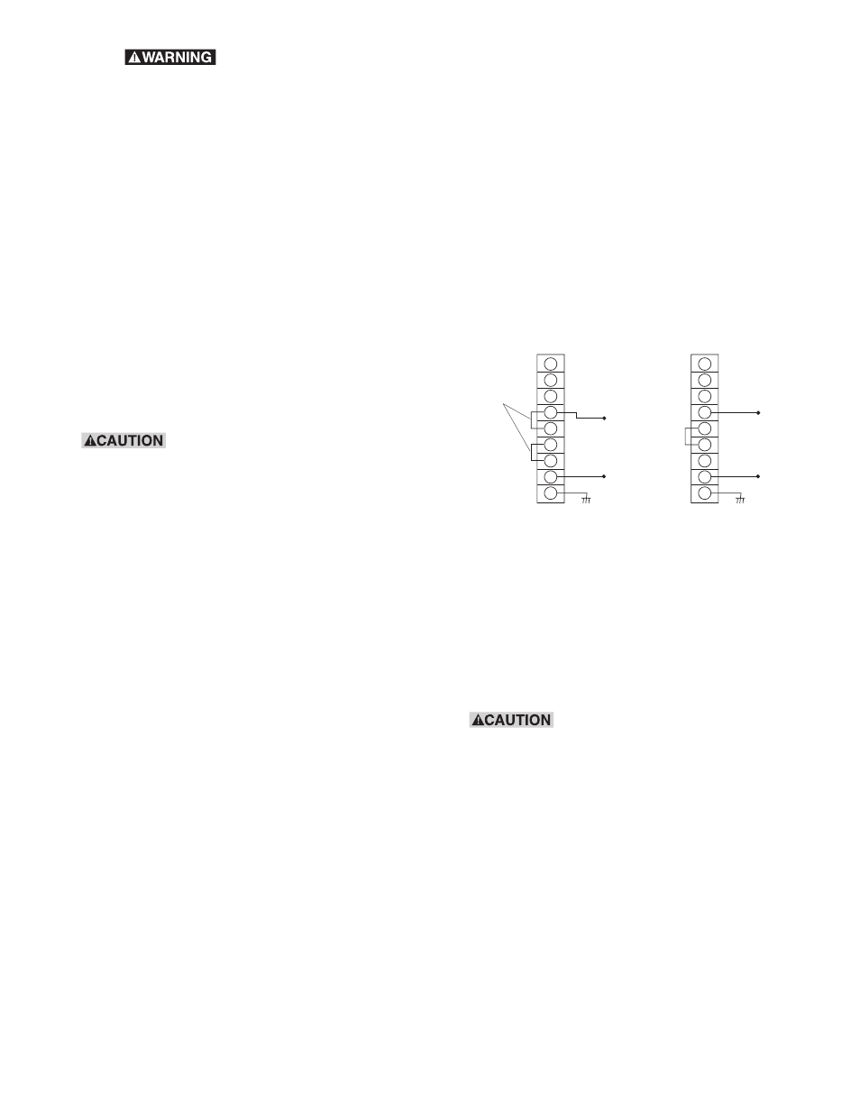
a. 115 AC Power Wiring b: 230 VAC Power Wiring
Figure 2
NEUTRAL
1
2
3
4
5
6
7
8
9
115 VAC
HOT
TB2
NEUTRAL
1
2
3
4
5
6
7
8
9
230 VAC
HOT
TB2
FACTORY
INSTALLED
JUMPERS
INSTALL
JUMPER
GND
GND
o 7. Do not attempt to incorporate
external switching schemes between two or
more brakes and the TCS-200-1 output. This will
damage the control and void the warranty.
o 8. Do not attempt to wire two or more controls in
parallel.
TCS-200-1 Series Controls Wiring
Refer to Figure 2 for actual wiring connections.
o 1. Unlatch the front cover of the TCS-200-1.
Power
Determine if 115 VAC or 230 VAC will be used to
power the control and proceed to that section of this
manual.
Insure power is off and disconnects
open on the control panel before connecting the AC
input. Failure to do so can result in damage to
equipment and injury or even death to personnel.
115 VAC
Refer to Figure 2a for 115 VAC power input
connections.
o 1. Connect the 115 VAC power to terminals 4 & 8
of terminal block TB2 located in the base of the
TCS-200-1 enclosure. Secure the terminal
screws.
o 2. Connect an earth ground wire between
terminal 9 of terminal block TB2 and an
unpainted metal surface of the control panel to
ensure a good ground connection. Secure the
terminal screw. Make sure the control panel itself
is properly grounded.
230 VAC Input
Refer to Figure 2b for 230 VAC power input
connection.
o 1. Remove the factory installed jumpers from
terminals 4 & 5 and 6 & 7 of terminal block TB2
located in the base of the TCS-200-1 enclosure.