All other 2 wire tension brakes, Remote torque adjust input (optional), Electro disc tension braking system figure 3a – Warner Electric TCS-200-1H User Manual
Page 8: All other 2 wire tension brake wiring figure 3b
8
Warner Electric • 800-825-9050
P-2003-2 • 819-0420
o 2. In a system with more than one magnet,
connect the remaining red wires from magnets
2 through 16 to terminal 2 of terminal block TB2
of the TCS-200-1.
o 3. Connect all black magnet wires to terminal 3
of terminal block TB2 of the TCS-200-1.
Note: Magnets of the Electro Disc tension brake
must be properly connected, otherwise the control
system will not function properly.
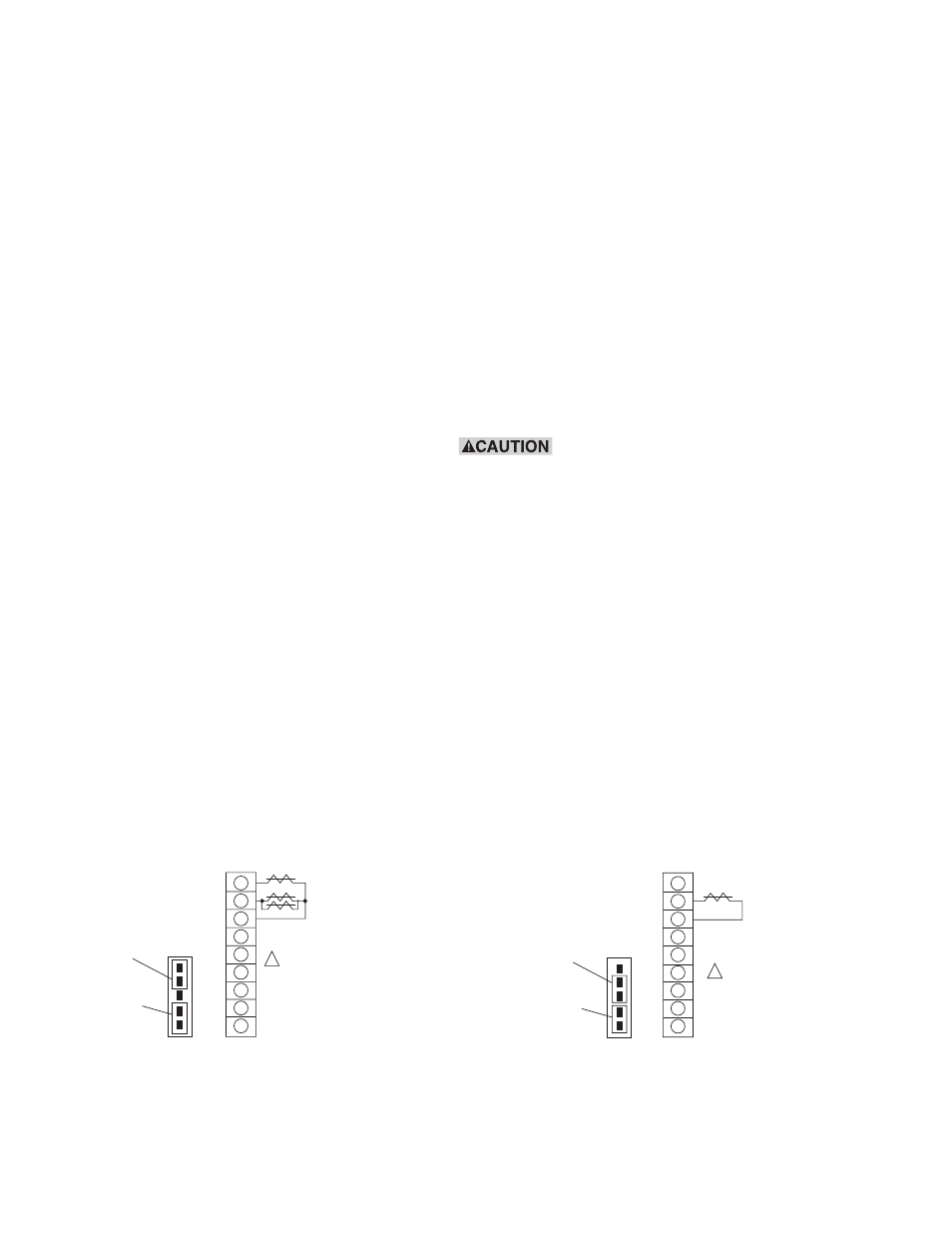
All Other 2 Wire Tension Brakes
To connect all other 2-wire tension brakes [Warner
Electric’s Magnetic Particle Brakes, Precision Tork
Magnetic Particle Brakes, TB series brakes, or
Advanced Technology (AT) tension brakes], refer to
Figure 3b for 2-wire tension brakes wiring
connections.
o 1. Connect one wire from the brake magnet
to terminal 2 of terminal block TB2 of the
TCS-200-1. Secure the terminal screw.
o 2. Connect the second wire from the brake
magnet to terminal 3 of terminal block TB2 of the
TCS-200-1. Secure the terminal screw.
o 3. Locate the five position jumper in the inside
cover of the TCS-200-1. Move the 2-position
black selector jumper from positions 1 & 2 to 2 &
3. This allows the control to operate without a
brake sense magnet.
Remote Torque Adjust Input (Optional)
Refer to Figure 4a for remote torque adjust input
connections.
o 1. Wire a three conductor shielded cable to the
remote sensor potentiometer previously installed.
Note: Using a shielded cable with wire colors red,
black, and green is recommended to simplify
potentiometer and terminal connections:
a. Black wire to low resistance end terminal of
potentiometer.
b. Red wire to high resistance end terminal of
potentiometer.
c. Green wire to wiper terminal of potentiometer.
Do not connect the shield lead of the
cable at the potentiometer end. Cut the shield
lead off at this end.
o 2. Route the cable from the sensor potentiometer
to the control, keeping the cable segregated from
high voltage AC power lines and other wiring that
may cause noise transients.
o 3. Connect the black wire from the low
resistance end of the remote potentiometer to
terminal 11 of terminal block TB1 in the
TCS-200-1. Snug terminal only.
o 4. Connect the green wire from the wiper of the
remote potentiometer to terminal 9 of terminal
block TB1 in the TCS-200-1. Secure the terminal
screw.
#1 RED
1
2
3
4
5
6
7
8
9
TB2
RED
BLK
2 THRU 16
BRAKE
MAGNETS
BRAKE
SENSE
BRAKE
RETURN
DO NOT WIRE MORE
THAN ONE MAGNET
BETWEEN TERMINALS
TB2, 1 AND TB2, 3.
!
1
2
3
4
5
JP1
CAUTION
SEE FIG. 5
FOR JUMPER
REMOVAL.
INSTALL THIS
JUMPER FOR
APPLICATIONS
NOT USING
ANALOG INPUTS.
PLACE JUMPER
HERE FOR
ELECTRO DISC
BRAKES
Electro disc tension braking system
Figure 3a.
PLACE JUMPER
HERE FOR
2 WIRE TENSION
BRAKES
1
2
3
4
5
JP1
1
2
3
4
5
6
7
8
9
TB2
BRAKE
BRAKE
SENSE
BRAKE
RETURN
DO NOT WIRE
ANY MAGNETS
ON TB2, 1.
!
CAUTION
SEE FIG. 5
FOR JUMPER
REMOVAL.
INSTALL THIS
JUMPER FOR
APPLICATIONS
NOT USING
ANALOG INPUTS.
All other 2 wire tension brake wiring
Figure 3b.