Analog input (optional) – Warner Electric TCS-200-1H User Manual
Page 10
10
Warner Electric • 800-825-9050
P-2003-2 • 819-0420
Do not connect the shield lead of the
cable at the switch contacts. Cut the shield lead
off at this end.
o 3. Route the remote mode switch cable to the
control, keeping the cable segregated from high
voltage AC power lines and other control wiring
that may cause noise transients.
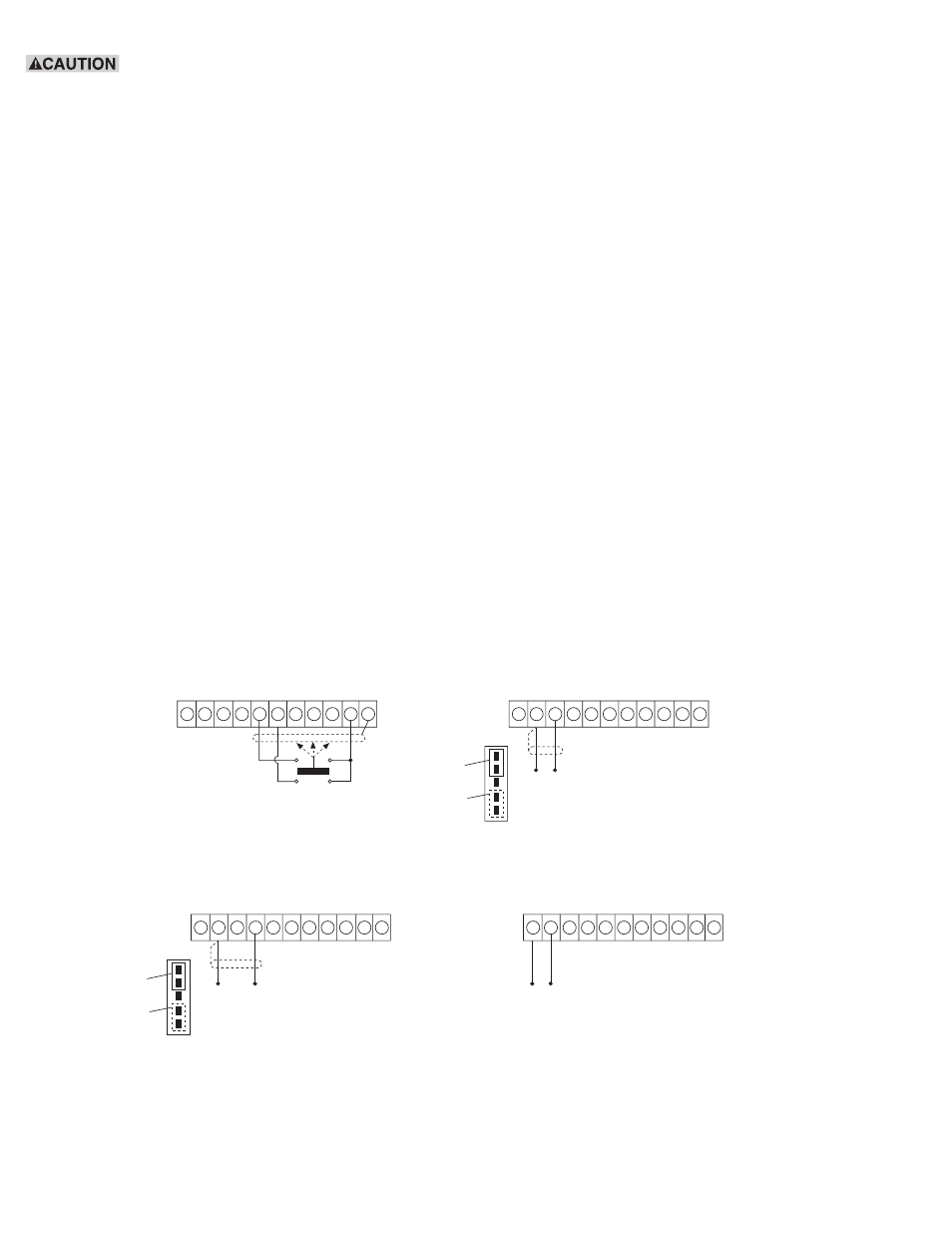
o 4. Connect the black wire from the switch
common contacts of the remote mode switch to
terminal 10 of terminal block TB1 of the
TCS-200-1. Tighten the screw.
o 5. Connect the red wire from the normally open
contact for the “on” or “stop” position of the
remote mode switch to terminal 5 of terminal
block TB1 of the TCS-200-1. Tighten the screw.
o 6. Connect the green wire from the normally
open contact for the “off” position of the remote
mode switch to terminal 6 of terminal block TB1
of the TCS-200-1. Tighten the screw.
o 7. Connect the shield wire from the cable to
terminal 11 of terminal block TB1 of the
TCS-200-1. Securely tighten the screw.
The TCS-200 Tension Control has now been wired
for operation. Before applying power to the system,
double check the wiring and installation for proper
connection. After this check has been completed,
proceed to the start-up and adjustment section of
this manual.
Analog Input (Optional)
Two options for the analog input signal are available.
These include 0-10 VDC or 4-20 mA signal.
Determine which signal will be supplied and refer to
the proper section of this manual below. Also,
determine if this input needs to be isolated from the
control ground. For example, if a PLC is used, this
input must be isolated. Then refer to the Isolation
section of this manual.
Note: A shielded cable is recommended for the 0-10
VDC or 4-20 mA input to insure a good signal.
0-10 VDC
Refer to Figure 5b for the 0-10 VDC analog input
connections.
TB1
1 2 3 4 5 6 7 8 9 10 11
STOP
ST
OP
SIGNAL
COMMON
OFF
RUN
+15V
OFF
SIGNAL
TB1
1 2 3 4 5 6 7 8 9 10 11
ISO COMMON
0-10VDC
0-10VDC
INPUT
-
+
1
2
3
4
5
JP1
SEE FIG. 3
FOR THIS
JUMPER
LOCATION
REMOVE
THIS JUMPER
JP1-4 AND 5
FOR ANALOG
INPUT
1
2
3
4
5
JP1
SEE FIG. 3
FOR THIS
JUMPER
LOCATION
REMOVE
THIS JUMPER
JP1-4 AND 5
FOR ANALOG
INPUT
TB1
1 2 3 4 5 6 7 8 9 10 11
ISO COMMON
4-20m
A
4-20mA
INPUT
-
+
TB1
1 2 3 4 5 6 7 8 9 10 11
ISO COMMON
15-35V
15-35VDC
ISOLATION
SUPPLY
-
+
a. Remote mode selector switch
b. 0-10v analog input
c. 4-20mA analog input
Figure 5
d. Isolation power supply