Warner Electric PB-650 Pin Drive User Manual
Page 5
5
Warner Electric • 800-825-9050
819-0485
D. Mounting the Armature Assembly
The armature and armature hub are mounted on
the shaft with a taperlock bushing. All parts
must be clean and free from burrs and chips
before assembling.
1. Place the bushing into the hub and insert the
key. The key is a side-to-side fit and should
not contact the top of the keyway.
2. Insert the locking setscrews into the bushing
and slide the assembly onto the shaft.
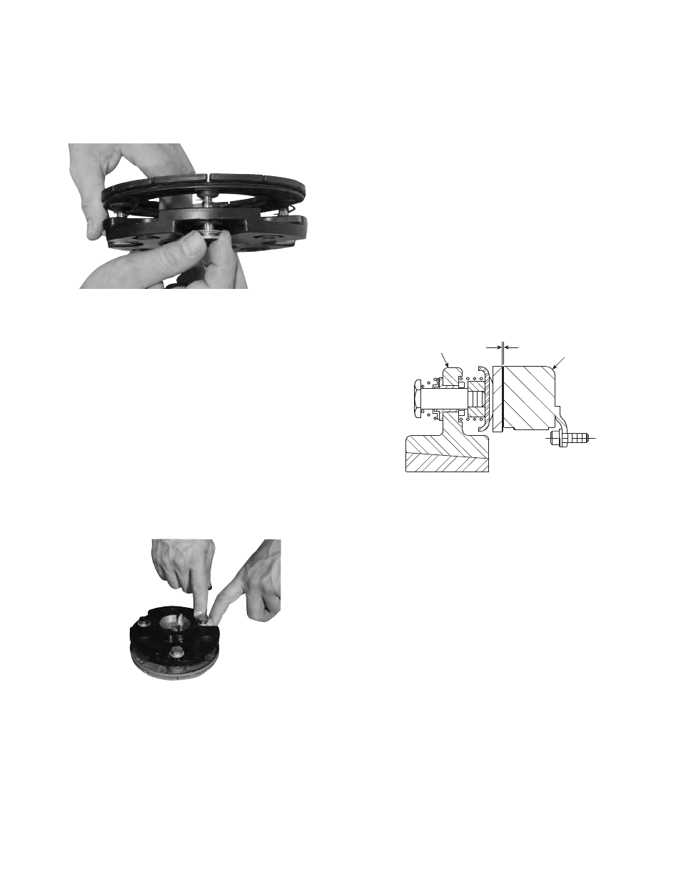
3. Place the face of the armature approximately
1/32" from the face of the magnet. Once this
gap is set, it will be automatically maintained
throughout the life of the unit. (Figure 10)
4. Securely fasten the armature assembly to the
shaft by alternately tightening each setscrew.
During the tightening process, the bushing
should be tapped lightly to make certain it
seats-in properly.
Step 4
Insert assembled drive pins through armature
hub and straight springs and into the threaded
armature bosses. Apply grade "AA" Loctite
Sealant on drive pin threads. (Figure 8)
Step 5
Tighten drive pins until shoulders of pins are
against face of armature bosses. Since threads
are class No. 3 fit, pins may seem to bind.
Figure 8
1/32-inch
Armature
Magnet
Step 6
Compress the retainers against the armature
hub and check to see that the armature hub is
held tightly to the armature bosses.
Note: This position must not be disturbed
during completion of assembly. (Figure 9)
Figure 10
Figure 9