Warner Electric PB-650 Pin Drive User Manual
Page 17
17
Warner Electric • 800-825-9050
819-0485
3
2
1
7
6
5A
5A-1
4A
6
5B-1
5C-1
5B
5C
4B
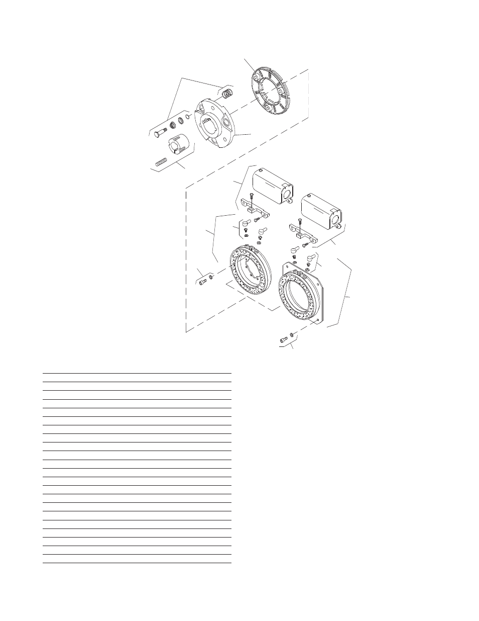
PB-500 Brake Normal Duty
Drawing I-25544
How to Order:
1. Specify Bore Size for Item 7.
2. Specify Voltage for Items 5A, 5B, or 5C.
3. Specify Inside Mounted for Item 5A and
Outside Mounted (Offset) for Item 5B or
Outside Mounted (Flush) for Item 5C.
Example:
PB-500 Brake per I-25544 - 90 Volt, Inside
Mounted, 3/4" Bore
These units, when used in conjunction with the
correct Warner Electric conduit box, meet the
standards of UL508 and are listed under guide
card #NMTR, file #59164. These units are CSA
certified under file #LR11543.
Item
Description
Part Number
Qty.
1
Armature Hub
5300-541-004
1
2
Armature
5300-111-002
1
3
Autogap Accessory
5200-101-009
3
4A
Mounting Accessory - I.M.
5102-101-001
2
4B
Mounting Accessory - O.M.
5300-101-008
1
5A
Magnet - I.M.
1
6 Volt
5300-631-002
24 Volt
5300-631-003
90 Volt
5300-631-005
5A-1
Terminal Accessory
5311-101-001
1
5B
Magnet - O.M. - Offset
1
90 Volt
5300-631-014
5B-1
Terminal Accessory
5311-101-001
1
5C
Magnet - O.M. - Flush
1
6 Volt
5300-631-009
24 Volt
5300-631-010
90 Volt
5300-631-011
5C-1
Terminal Accessory
5311-101-001
1
6
Conduit Box
5200-101-010
1
7
Bushing*
1/2" to 1-1/4" Bore
180-0116 to 180-0128 1
*See page 22 for specific part numbers.