Teledyne LeCroy IBTracer 4X - Users Manual Ver.2.20 User Manual
Page 20
12
IBTracer 4X Protocol Analyzer User’s Manual
CATC
SW Version 2.2
Center-most LEDs and Button
The LEDs and button on the UPAS enclosure function in conjunction with
the IBTracer 4X module inserted above it.
•
Green REC (recording) LED (lights when the unit is recording).
•
Orange TRG (triggered) LED (lights when the unit triggers an event).
•
Green UPLD (Upload) (lights when unit is uploading data to PC).
•
MANUAL TRG (Manual Trigger) push-button (allows a manual Trace
capture).
Right-most LEDs and Button
The LEDs and button under the right module slot are reserved for future
releases of hardware modules.
•
Green REC (recording) LED (lights when the unit is recording).
•
Orange TRG (triggered) LED (lights when the unit triggers an event
TRG also lights during power-on testing and will be turned off at the end
of the power on cycle. If the LED blinks at the end of this cycle, the
hardware is faulty).
•
Green UPLD (Upload) LED (lights when unit is uploading data to PC).
•
MANUAL TRG push-button (allows a manual Trace capture).
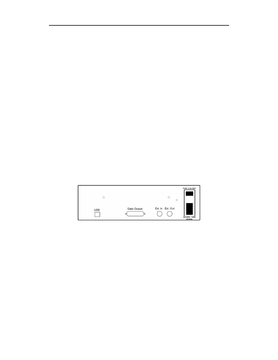
Figure 2: Universal Protocol Analyzer Rear Panel and its connectors
• Wide range AC connector module
—
Power socket
—
Enclosed 5x20 mm 2.0A 250 V fast acting glass fuse
Warning: For continued protection against fire, replace fuse only with the
type and rating specified above.
—
Power on/off switch
• Two External Ports marked Ext. In and Ext. Out
• USB 2.0 type B host computer connector
• Data In/Out DB-25 (25-pin) external interface connector