3 merlin rear panel description, Merlin rear panel description – Teledyne LeCroy Merlin - Users Manual User Manual
Page 18
10
Merlin Protocol Analyzer User’s Manual
CATC
SW Version 2.0
•
Green SYNC (synchronized) LED (lights when the unit is locked onto a
specific piconet, based on the Master Address).
•
Manual Trigger push-button (allows a manual Trace capture)
— After beginning a recording session, press the Manual Trigger switch to
force a Trigger condition. The session completes when a specified
post-Trigger amount of bus data is recorded or when you manually stop a
recording session.
•
ANT Bluetooth™ Antenna connector
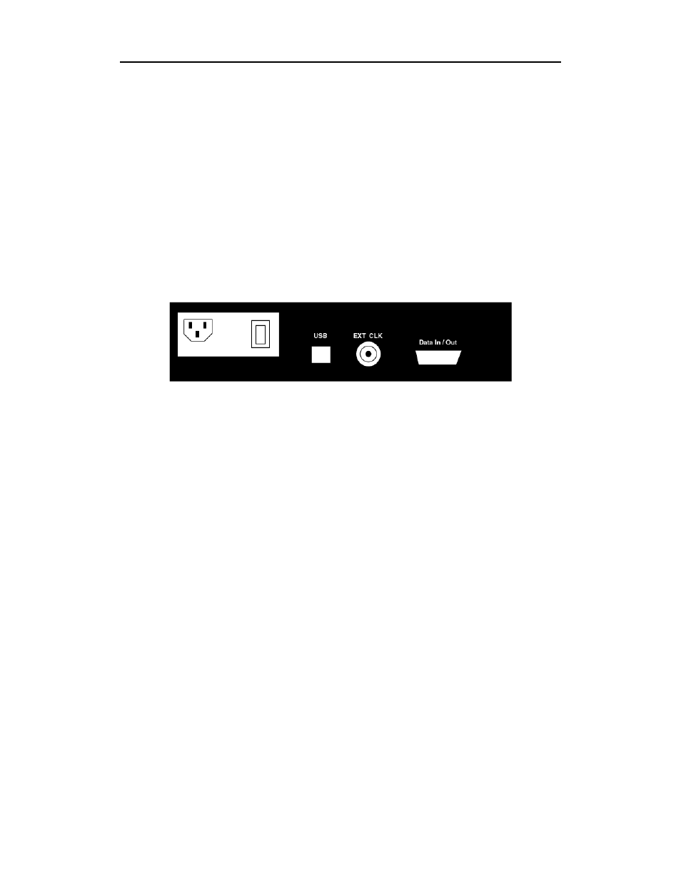
2.3 Merlin Rear Panel Description
Figure 2: Rear Panel
From left to right, the rear panel has the following connectors and switches:
Wide Range AC Connector Module
The power module is composed of:
—
Power on/off switch
—
Power socket
—
Enclosed 5x20 mm 2.0A 250 V fast acting glass fuse
Warning For continued protection against fire, replace fuse only with the type
and rating specified above.
USB type "B" host computer connector
This is the connector that is used to link the analyzer to the PC that will be
administering it.
BNC Connectors "Ext. In" and "Ext. Out"
These connectors allow BNC cables to be attached to the analyzer for the
purpose of triggering on external input signals.
RS-232 25 pin "Data Output" Connector
This connector attaches to a 25 pin RS-232 cable that in turn attaches to an
External Breakout board. The breakout board allows signals to be sent from
the analyzer to an external device such as an oscilloscope.