Maintenance and assembly, Operation, Lubrication – Foredom K.500 User Manual
Page 2: Shaft replacement, Adjustment of shaft and sheath, Set up, H.60 massager handpiece maintenance
Operation
For the best performance, safety, and
maximum life, please follow these
general suggestions:
1. Try to avoid using the Massager with
sharp bends or loops in the flexible shaft.
This will reduce wear of the flexible shaft
and the sheath lining.
2. Never deliberately stall the motor or slow
it down near the stalling point by bearing
down too hard on the handpiece.
3. The Massager comes with a dial control
built into the base. Strokes can be varied
from 0 to 4,400 per minute with the turn
of the dial.
Maintenance and
Assembly
These simple maintenance procedures
should be done by the user:
1. Cleaning and lubrication of flexible shaft
and handpiece.
2. Replacement of motor brushes.
3. Replacement of worn shafts
and sheaths.
4. Replacement of handpiece pads.
Keep the Massager as free of dust and
dirt as possible. Never allow oil or
grease to accumulate on exposed
surfaces as this tends to collect dirt.
Lubrication
The motor has permanently lubricated bear-
ings and does not require lubrication.
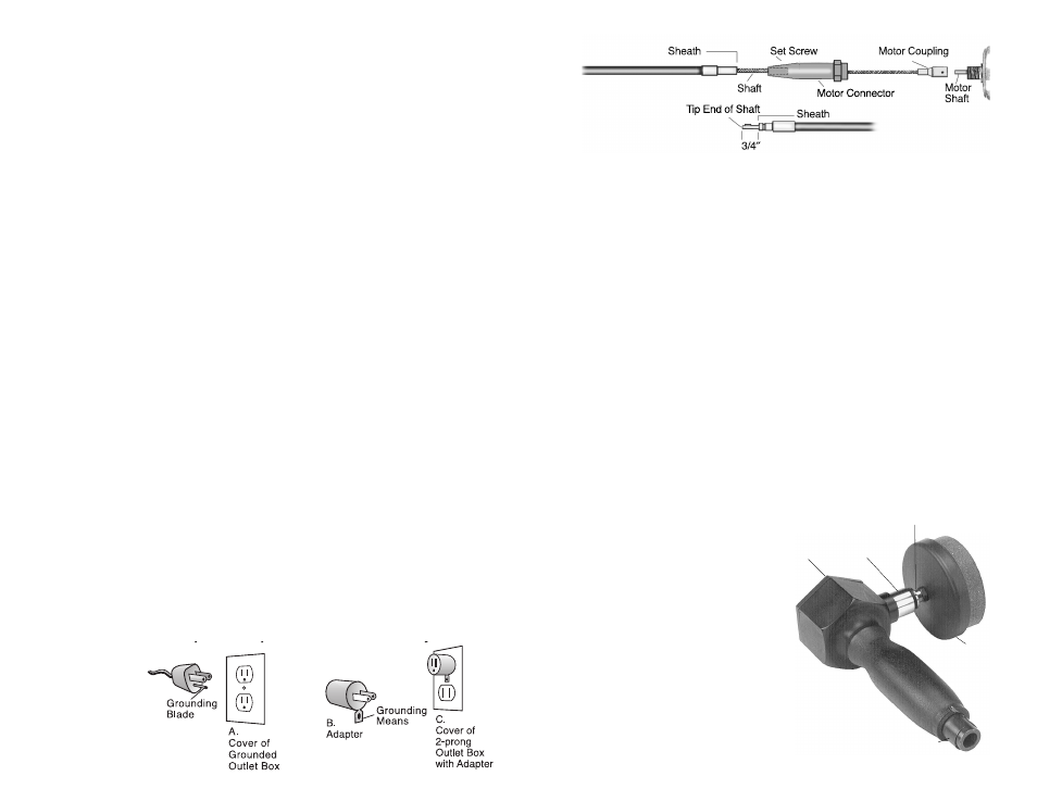
The flexible shaft should be cleaned and
lubricated once every 100 hours of use.
Expose the shaft by removing the handpiece
and then the sheath by loosening the set
screw in the motor connector (see Figure 1)
and sliding it off the shaft. Apply a light film
of Foredom flexible shaft grease (MS10006)
along the entire length of the shaft after wip-
ing off the old grease with a piece of cloth.
Replace the sheath by sliding it over the shaft
and tightening the set screw. Be sure to
follow the Adjustment Instructions below.
Shaft Replacement
1. Remove the motor connector. Left hand
thread, turn right. (See Figure 1)
2. Loosen the set screw on the old flexible shaft
motor coupling and slide the shaft coupling
off the motor shaft. (See Figure 1.) Tighten
the set screw of the new shaft onto the flat
on the motor shaft.
3. Put the motor connector back on the motor
by sliding it up the flexible shaft and tighten-
ing. Grease shaft as described above.
4. Now slide the sheath over the flexible shaft
with the plain sheath fitting (not the grooved
fitting) going toward the motor and into the
motor connection.
Adjustment of Shaft and Sheath
Before attaching handpiece, shaft and sheath
adjustment must be carefully checked. Place
the entire unit on a flat surface with shaft and
sheath extended straight. Adjust the exposed
tip of the flexible shaft so that it extends 3/4
″
beyond the sheath, as shown above. This is
done by moving the sheath in or out of the
Front
Plate
Set Screw
Adjustment
Sleeve
Plunger Shaft
Handpiece
Pad Holder
Figure 1
Figure 2
Set Up
Check the voltage of your power before
plugging in the motor. It should match the
voltage shown on the motor nameplate.
Models 500 and 500L are for use on 115
Volt AC power. Models 500-2 and 500L-2
are for use on 230 Volt AC power.
Note: The Massager Handpiece comes
attached to the motor. If you need to remove
the handpiece (when cleaning, for example),
loosen the set screw and just pull away from
the shaft and sheath with a strong motion.
To reattach, push the handpiece onto the
shaft tip and sheath fitting while motor is
running slowly. Be sure that the catch ball in
the end of the handpiece toward the sheath
goes into the groove in the sheath tip so
that the handpiece will be held securely onto
the sheath.
motor connector. When the correct adjust-
ment is made, tighten the screw in the motor
connector. The handpiece can now be
reattached as described in the Note: under
“Set Up”.
H.60 Massager Handpiece
Maintenance
The handpiece should be cleaned and
lubricated once every 100 hours of use.
Remove the Front Plate to expose the
eccentric cam and plunger shaft. Flush out
the old grease with a solvent and regrease
with a teaspoonful of Foredom grease,
being sure that all the moving parts are
thoroughly lubricated. After regreasing, run
the handpiece slowly for a few minutes to
fully distribute grease. The Adjustment
Sleeve retains a grease seal and should be
tightened to prevent leakage of grease.
•
Use proper grounding procedures. This tool
should be grounded while in use to protect
the operator from electric shock. The tool is
equipped with an approved 3-conductor cord
and a 3-prong grounding type plug to fit the
proper grounding receptacle. The green (or
green and yellow) conductor in the cord is the
grounding wire. Never connect the green (or
green and yellow) wire to a live terminal. If
your unit is for use on less than 150 volts, it
has a plug that looks like sketch A below. An
adapter (sketches B and C) can be used for
connecting plugs as shown in sketch A to
2-prong receptacles. The green colored rigid
ear, lug, etc., extending from the adapter must
be connected to a permanent ground such as
a properly grounded outlet box.
Some jurisdictions, including Canada,
prohibit the use of 3 to 2 prong adapters.
Where prohibited, they should not be used.
Use only 3-wire extension cords that have 3-
prong grounding type plugs and 3-pole type
plugs and 3-pole receptacles that accept the
tool’s plug. Always disconnect the power cord
before servicing the tool.
Replace a worn
cord immediately.
Models 500-2 and 500L-2 are equipped
with power plugs suitable for use in the
country for which they are intended.