IAI America IX-NNC3515 User Manual
Page 66
60
7. Specifi
cations
Item
Specifications
User piping
Three air tubes (outer diameter: 4, inner diameter: 2.5)
(normal service pressure: 0.8 MPa)
Temperature: 0 to 40 C, humidity: 20 to 85%RH or less (non-condensing)
Altitude
m
1,000 or less
B
d
e
s
i
o
N
71
Robot weight
kg
20
Cleanliness class
Class 10 (0.1- m base, with suction)
Suction rate (*10)
Nl/min
60 NI/min
230 V 50/60 Hz 5 A
Allowable supply voltage fluctuation
%
10
Overvoltage category (IEC60664-1)
Category III
Pollution degree (IEC60664-1)
Pollution degree 3
*1
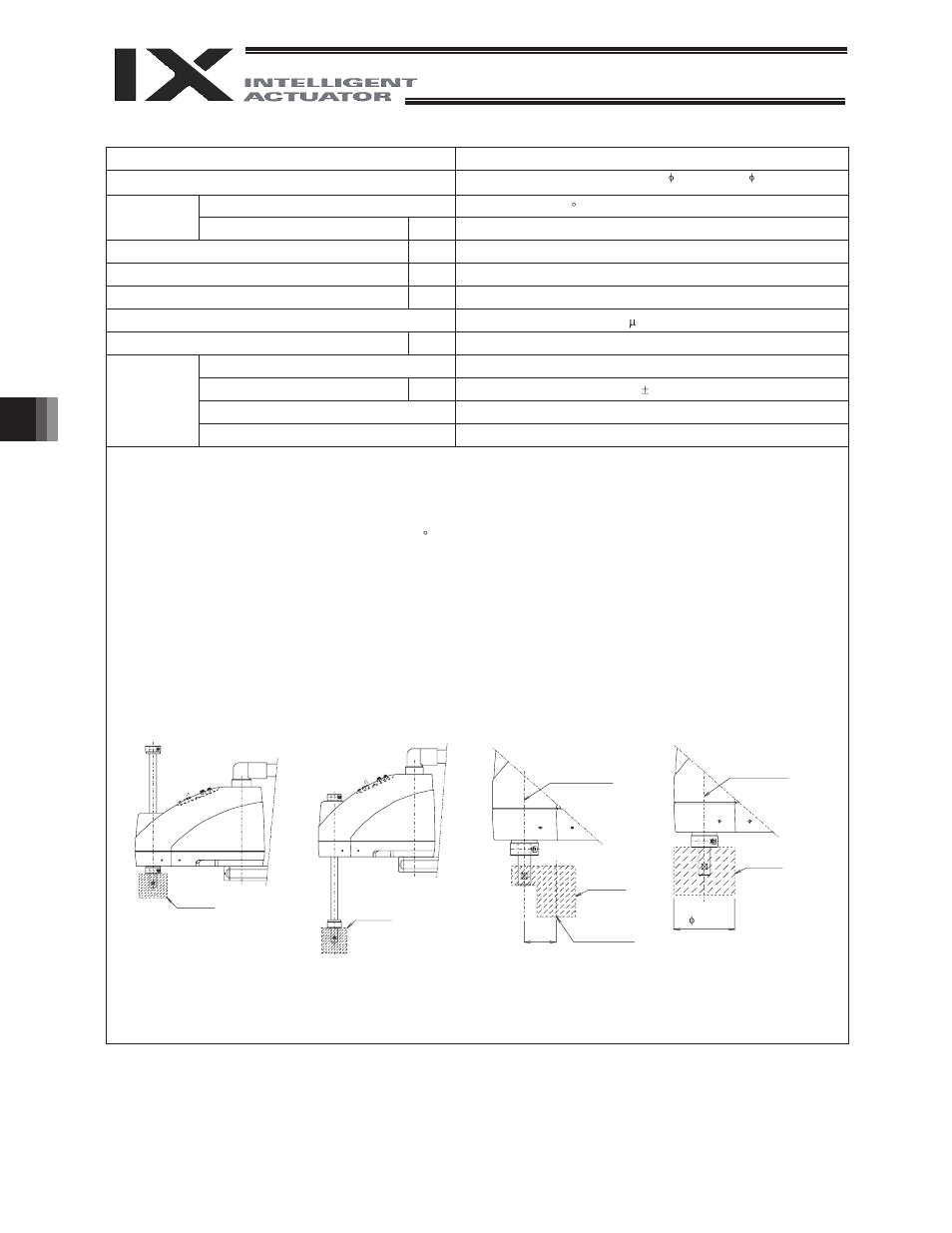
To move the robot horizontally at high speed, perform teaching so that the vertical axis stays as close to the top position as
possible. (Fig. 1)
To operate the robot with its vertical axis at the bottom position, the speed and acceleration must be reduced as appropriate.
(Fig. 2)
*2
Assuming PTP instruction operation.
*3
Measured at a constant ambient temperature of 20 C.
*4
Measured when the robot is operated at the maximum speed, carrying a load of 2 kg.
*5
A force of up to three times the dynamic push-in thrust may be applied at any given moment.
*6
The static thrust refers to thrust generated within the robot’ s range of operation based on PAPR instruction.
*7
The permissible moment of inertia converted to a value at the rotational center of axis 4. The offset from the rotational center of
axis 4 to the tool’ s center of gravityis assumed to be 40 mm or less. (Fig. 3)
If the tool’ s center of gravity is further away from the rota
tional center of axis 4, the speed and acceleration must be reduced as
appropriate.
*8
If the tool exceeds the permissible diameter, it will contact the robot inside the robot’ s range of movement. (Fig. 4)
*9
To enable the alarm LED indicator, the user must provide a circuit that supplies 24 VDC to the LED terminal in the user
connector in response to the controller I/O output signal, etc.
*10
A reference suction rate.
Reference design standards: Annex I to Machine Directives, EN292-1, EN292-2, EN1050, EN60204-1, EN775
Top position
Tool
Tool
Tool
Tool
Bottom
position
Center of
rotational axis
Center of
rotational axis
Tool’ s center
of gravity
(Fig. 1)
(Fig. 2)
(Fig. 3)
(Fig. 4)
50
100
Brake power source for main unit
W
24V DC ±10% 10W
Operating
environment
Ambient temperature/humidity
Controller
Power supply