IAI America IX-NNC3515 User Manual
Page 42
36
6. Inspection/Maintenance
6.2.8
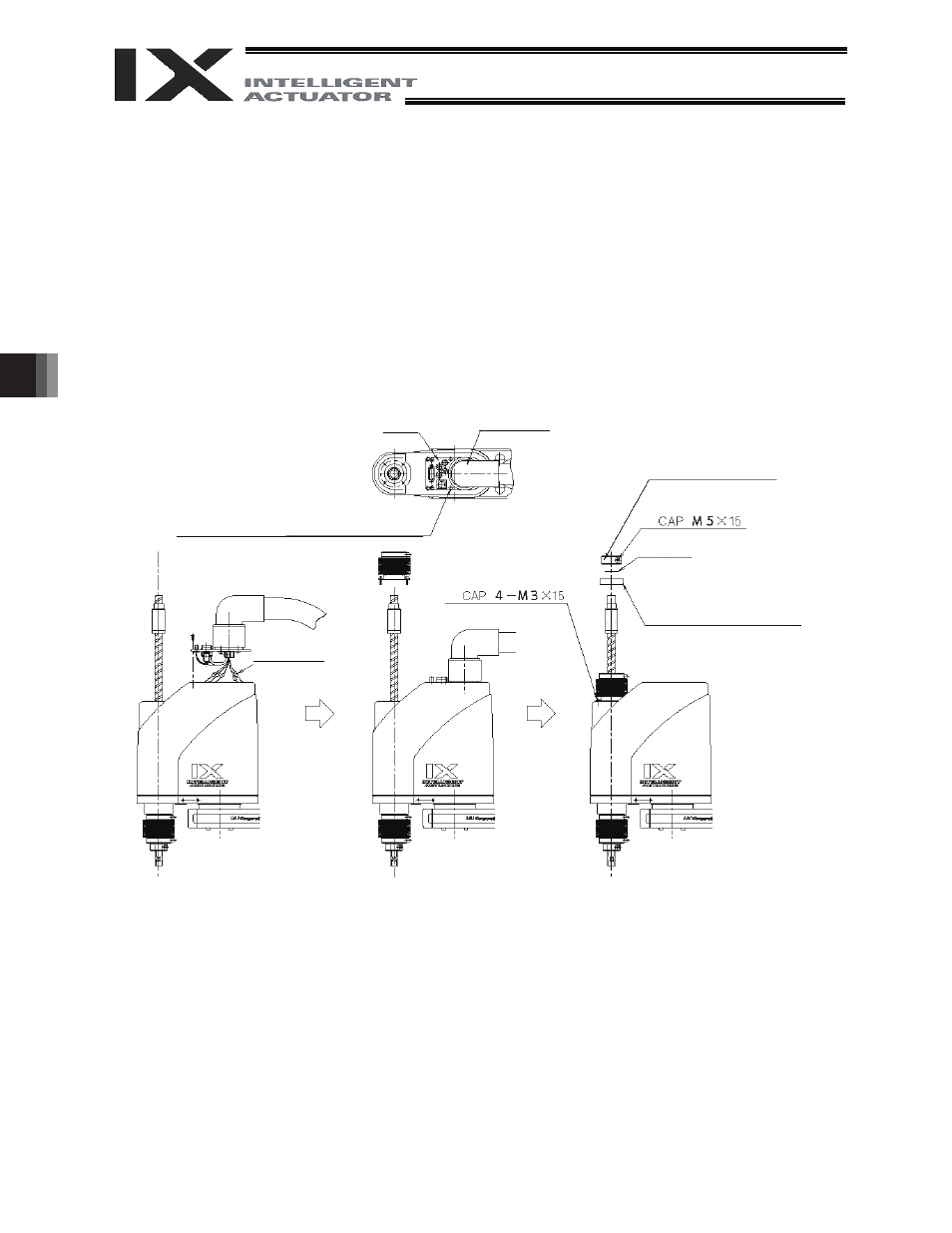
Installing the Cover
(1) Install the cover and connect the motor connectors (M, PG, BK) extending from the rotary joint.
(2) Affix the panel using the six countersunk head screws [1] by paying attention not to cause the wires
to rest on top of one another.
(Place the wires neatly in the upper space without letting them rest on top of one another. Do not
forcibly tighten the screws with the panel still floating.)
(3) Tighten the four cap screws (M3 x 15) [2] to affix the bellows.
(4) Install the bearing case, gasket and stopper in this order, and tighten the stopper using the cap screw
(M5 x 15) [3].
Rotary joint
[1] 6 - M3 x 4 (countersunk head screw)
Panel
Connect the connectors
(M, PG, BK).
[2]
[3]
Stopper
(Must be installed in the correct
orientation: The side showing two
tapped holes should face up.)
Gasket
Bearing case
(Must be installed in the correct
orientation: The side showing the entire
side face of the bearing should face up.)