4 wiring diagram, 81 7. speci fi cations – IAI America IX-INN8040 User Manual
Page 87
81
7. Speci
fi cations
Notes (1)
The actual la
yout
of board conn
ec
tors varies from t
his draw
ing.
(2)
Since the brake
po
w
er circuit is prov
ided on t
he p
rimary
side
(high-volt
age side),
a d
edicated 24 V
po
w
er suppl
y is re
quire
d for this
circuit.
The 24 V po
w
er suppl
y for
I/O
circuit
s used on the secondary side (l
ow-volt
age side) cannot be
shared.
(3)
To ope
rate the
alarm LED, the
user must provide
a circuit that uses the controller I/
O output signal.
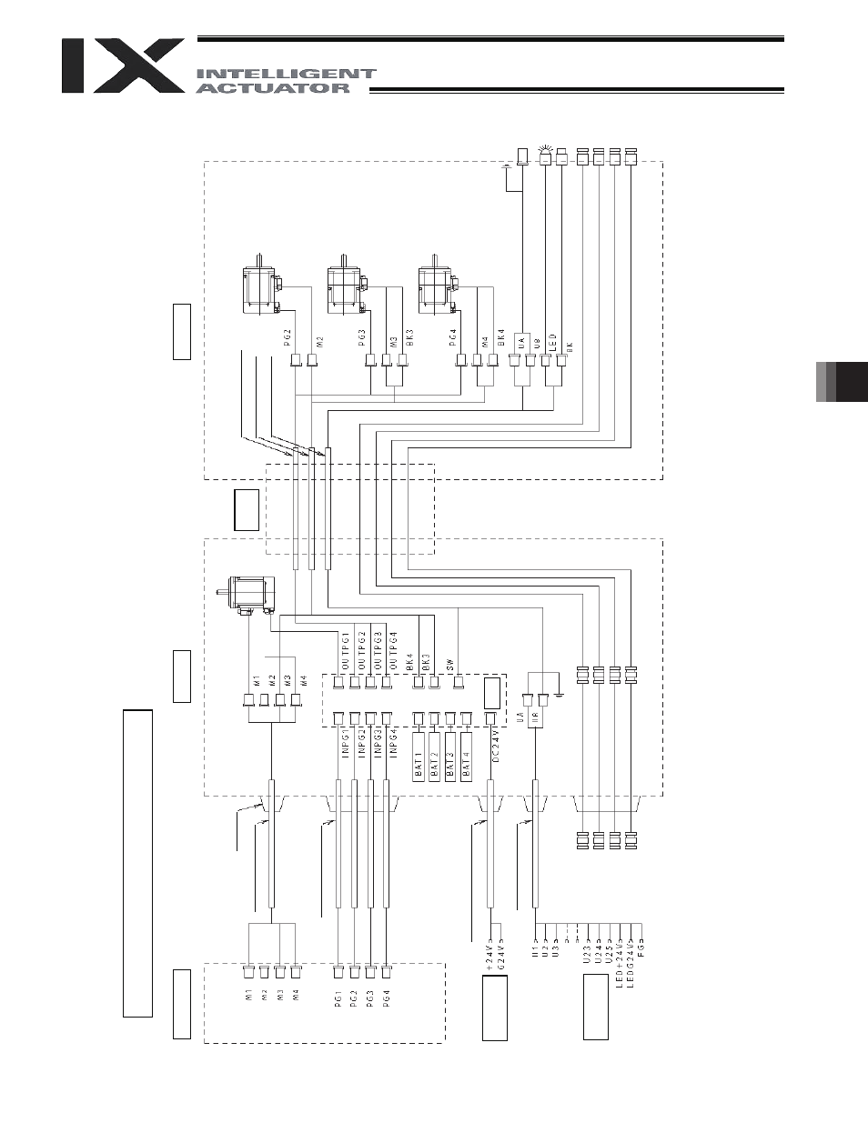
7.4 Wiring
Diagram
Wirin
g/Piping
Diagram (Arm Length: 500/600)
Co
nt
ro
lle
r
C
abl
e f
ix
cap
(C
apcon)
M c
ab
le
(ou
ts
ide
ro
bo
t)
P
G
c
ab
le
(o
uts
ide
ro
bot
)
BK p
ow
er
cabl
e (
ou
tsi
de r
ob
ot)
U cable (
out
sid
e r
obot)
Br
ake p
ow
er
term
in
als
Use
r w
irin
g
term
in
als
Insi
de bas
e
S
erv
o
m
oto
r f
or a
xis
1
(a
rm
1
)
Boar
d
FG (
To
bas
e)
A
ir joint, red (
6)
A
ir jo
in
t, y
ellow
(
6)
A
ir joint, bl
ack (
4)
A
ir joint, w
hite (
4)
Fle
xib
le
cabl
e
Insi
de ar
m 2
PG ca
bl
e (
insi
de
robo
t)
M
cable (
insid
e r
ob
ot)
U cable (
insid
e r
ob
ot)
Ser
vo
mot
or
for
ax
is
2
(a
rm
2
)
Ser
vo mot
or
w
ith br
ake
fo
r a
xis 3
(Z-a
xi
s)
Ser
vo mot
or
w
ith br
ake
for
ax
is
4 (
R
-ax
is
)
FG (
to D-
sub
ho
usi
ng
)
D-
su
b
co
nn
ec
tor
for
u
se
r w
iri
ng
(25-
pi
n, s
oc
ke
t)
A
la
rm
LE
D
Br
ake-
re
leas
e sw
itch for
ax
es 3/4
(Z
/R-
ax
es)
A
ir joint, red (
6)
A
ir jo
in
t, y
ellow
(
6)
A
ir joint, bl
ack (
4)
A
ir joint, w
hite (
4)
72