Warning – IAI America IX-INN8040 User Manual
Page 35
29
5. Precautions for Use
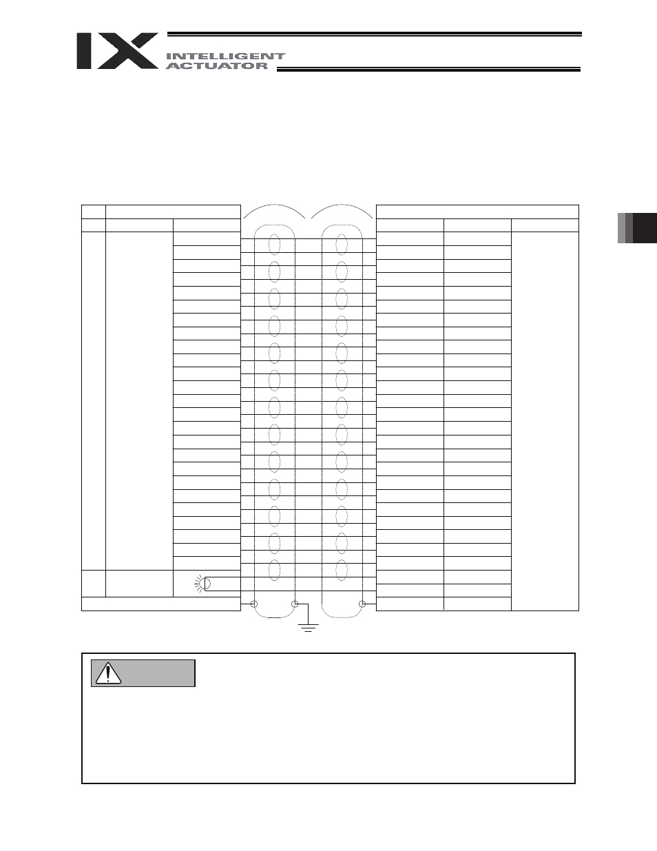
The robot comes with a 25-pin plug for the D-sub connector for user wiring.
Solder a user-supplied cable to the D-sub connector (plug), attach the supplied hood, and then connect to
the user connector (socket). Use a shielded cable with an outer diameter of 11 or less.
To turn on the indicator, the user must configure a dedicated circuit that uses the controller I/O output signal,
etc.
User connector pins and corresponding Y-terminals
Before commencing wiring/piping work, turn off the power to the controller and the power/air
supplies to the robot. Failure to do so may cause the robot to malfunction.
Use cables and tubes within their specifications. Failure to do so may result in fire or short circuit
due to an overheated cable, or may cause air leaks.
Connect the shielded cable to the hood. Otherwise, the robot may malfunction due to noise.
Secure the supplied D-sub connector using the screws on the hood.
To base
Inside unit
Cable
Arm 2 side
Connection
D-sub,
25-pin
Indicator
(LED)
To D-sub connector frame
Controller side
Y-terminal designation
Wire color
Orange 1 red
Light gray 1 red
Connection
Y-terminal
Orange 1 black
Light gray 1 black
White 1 red
White 1 black
Yellow 1 red
Yellow 1 black
Pink 1 red
Pink 1 black
Orange 2 red
Orange 2 black
White 2 red
White 2 black
Yellow 2 red
Yellow 2 black
Pink 2 red
Pink 2 black
Orange 3 red
Orange 3 black
Light gray 2 red
Light gray 2 black
Light gray 3 red
Light gray 3 black
White 3 red
White 3 black
Yellow 3 red
Green
No.
1
2
3
4
5
6
7
8
9
10
11
12
13
14
15
16
17
18
19
20
21
22
23
24
25
U1
U2
U3
U4
U5
U6
U7
U8
U9
U10
U11
U12
U13
U14
U15
U16
U17
U18
U19
U20
U21
U22
U23
U24
U25
LED +24V
LED G24V
FG
User Connector
ALM
Warning