Warning – IAI America IX-INN8040 User Manual
Page 58
52
6. Inspection/Maintenance
(8)
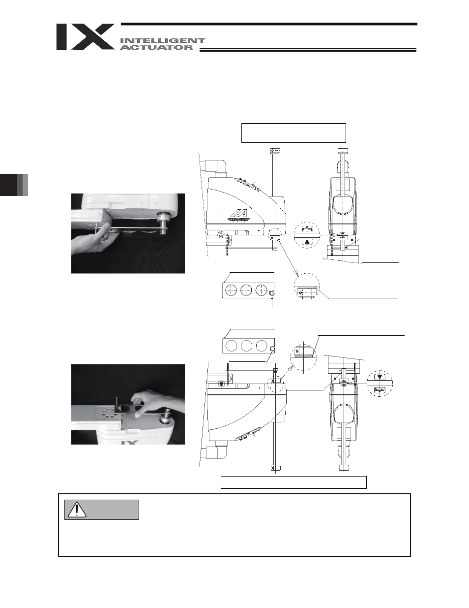
Affix the rotational axis at the reference position by setting the plate and pin of the adjustment jig as
illustrated below.
Set the jig after confirming that the emergency-stop switch is pressed.
Set the jig after adjusting the rotational axis to the reference position, using the positioning mark
label as a guide.
The top face of the stopper should roughly align with the bottom face of arm 2.
Always press the emergency-stop switch before setting an adjustment jig. Failure to do so may
cause the robot to malfunction and result in a serious accident.
Pay attention to the orientation of the D-cut surface of the plate jig.
Reference position of
ceiling-mount specification
D-cut surface
D-cut surface
The plate and pin should
make light contact.
Positioning
mark label for
rotational axis
The top face of the
stopper should align with
the bottom face of arm 2.
Warning
Reference position of inverse specification
The plate and pin should
make light contact.
D-cut surface
D-cut surface
The end face of the stopper should
align with the end face of arm 2.
Positioning mark
label for axis 4