Teaching pendant function and specification, Rs232c cable – IAI America DS-S-T1 User Manual
Page 11
Page 9
5.
Teaching Pendant Function and Specification
5.4
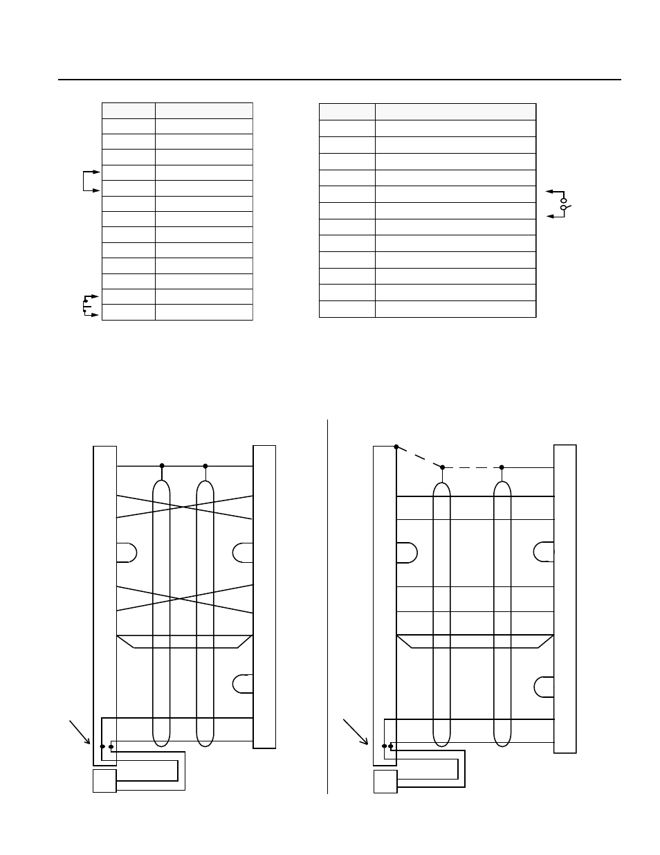
RS232C Connector (D-Sub 25 DTE Special*) for the DS Type
.
o
N
n
i
P
.
o
N
n
i
P
.
o
N
n
i
P
.
o
N
n
i
P
.
o
N
n
i
P
e
m
a
N
l
a
n
g
i
S
e
m
a
N
l
a
n
g
i
S
e
m
a
N
l
a
n
g
i
S
e
m
a
N
l
a
n
g
i
S
e
m
a
N
l
a
n
g
i
S
1
G
F
2
D
X
T
3
D
X
R
4
)
S
T
R
(
5
)
S
T
C
(
6
R
S
D
7
G
S
8
C
N
9
C
N
0
1
C
N
1
1
C
N
2
1
2
S
G
M
E
3
1
1
S
G
M
E
.
o
N
n
i
P
.
o
N
n
i
P
.
o
N
n
i
P
.
o
N
n
i
P
.
o
N
n
i
P
e
m
a
N
l
a
n
g
i
S
e
m
a
N
l
a
n
g
i
S
e
m
a
N
l
a
n
g
i
S
e
m
a
N
l
a
n
g
i
S
e
m
a
N
l
a
n
g
i
S
4
1
C
N
5
1
C
N
6
1
C
N
7
1
C
N
8
1
t
u
p
t
u
O
V
2
.
6
+
9
1
E
L
B
A
N
E
0
2
R
T
D
1
2
C
N
2
2
C
N
3
2
W
S
p
o
t
S
y
c
n
e
g
r
e
m
E
W
S
.
G
M
E
4
2
C
N
5
2
)
2
.
6
+
(
V
O
)
*
*
*
*
*
*
• Pin numbers 12, 13, 18, 19, 23, 25 are for use with the teaching pendant signal. Do not connect these pins for RS232C.
• Pin numbers 4 and 5 are short-circuited.
• Pin numbers 12 and 13 are connected for emergency stop (B contact).
•
Pin numbers 18 and 19 are ENABLE SW connecting terminal.
■ RS232C Cable
Please use RS232 cable pin configuration (between controller and computer serial port).
FG
TXD
RXD
RTS
CTS
DSR
DTR
GND
1
2
3
4
5
6
20
7
PC Side
(25 Pin)
FG
TXD
RXD
RTS
CTS
DSR
DTR
GND
ENABLE
6V
EMG S1
EMG S2
1
2
3
4
5
6
20
7
19
18
13
12
Controller Side
(25 Pin)
Shield
Yellow
Orange
Orange
Orange
Brown
Yellow
Green
Brown
Green
Blue
Blue
Black
Black
Gray
Red
Red
White
Black
Black
White
Gray
Soldering
within
the shell
EMG S1
EMG S2
EMG SW Side
1
2
1
2
3
4
5
6
20
7
19
18
13
12
FG
TXD
RXD
RTS
CTS
DSR
DTR
GND
ENABLE
6V
EMG S1
EMG S2
Controller Side
(25 Pin)
PC Side
(9S)
2
3
8
7
4
6
5
RXD
TXD
CTS
RTS
DTR
DSR
GND
Soldering
within
the shell
Shield
SPMC-8DG
Orange
Orange
Blue
Green
Black
Brown
Black
Blue
Brown
Green
Gray
Gray
Red
Red
Black
Yellow
Yellow
1
2
Shield
Drain
Drain
SPMC-8DG
(The shield line is connected to the
shell clamp area)
EMG SW Side
EMG S1
EMG S2
White
Black
Warning
Please only use cables as specified in the charts above. Connection using other types of cables may cause breakdown in the PC interface area.