Main unit disassembly process, Main unit disassembly flowchart – Acer 5737Z User Manual
Page 65
Chapter 3
55
Main Unit Disassembly Process
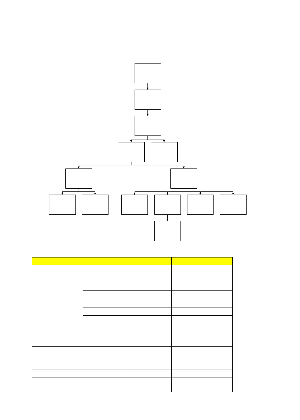
Main Unit Disassembly Flowchart
Screw List
Step
Screw
Quantity
Part No.
Switch Cover
M2.5*3
1
86.AZ802.006
Function Board
M2.5*3
1
86.AZ802.006
LCD Module
M2.5*8
4
86.AZ802.007
M2.5*6
2
86.AZ802.003
Upper Cover
M2.5*8
9
86.AZ802.007
M2.5*6
10
86.AZ802.003
M2.5*3
2
86.AZ802.006
TouchPad Bracket
M2*3
2
86.AZ802.002
Left Speaker
Module
M2.5*3
2
86.AZ802.006
Right Speaker
Module
M2.5*6
1
86.AZ802.003
USB Board
M2.5*6
1
86.AZ802.003
Mainboard
M2.5*6
3
86.AZ802.003
Thermal Module
CPU_SCREW_
SPRIN
4
N/A
Remove External
Modules before
proceeding
Remove
Mainboard
Remove
USB Board
Remove
Right Speaker
Module
Remove
Switch Cover
Remove
Keyboard
Remove
Upper Cover
Remove
Lower Cover
Remove
CPU
Remove
LCD Module
Remove
TouchPad
Bracket
Remove
Launch Board
Remove
Left Speaker
Module
Remove
Bluetooth Module
- Aspire 5741ZG (2345 pages)
- Aspire 5741ZG (313 pages)
- TravelMate 5330 (14 pages)
- Extensa 7230 (86 pages)
- AOD257 (1810 pages)
- AO753 (374 pages)
- AO533 (4 pages)
- AOD255 (299 pages)
- AO522 (1810 pages)
- Aspire V5-531G (2484 pages)
- Aspire EC-471G (10 pages)
- Aspire M3-581TG (11 pages)
- Aspire M3-581PTG (10 pages)
- Aspire M3-581TG (3478 pages)
- Aspire 8950G (378 pages)
- Aspire EC-471G (11 pages)
- Aspire V5-571PG (3604 pages)
- Aspire E1-571 (308 pages)
- Aspire E1-521 (11 pages)
- Aspire S5-391 (111 pages)
- Aspire S5-391 (11 pages)
- Aspire M5-581TG (10 pages)
- Aspire M5-581TG (11 pages)
- Aspire V3-471G (362 pages)
- Aspire V3-471G (11 pages)
- Aspire M5-481TG (11 pages)
- Aspire 9420 (109 pages)
- Aspire 9520 (123 pages)
- 3280 (106 pages)
- 4600 (128 pages)
- Aspire 1300 (96 pages)
- 4330 (198 pages)
- TravelMate 3250 (98 pages)
- 1450 (99 pages)
- 2420 (108 pages)
- 310 (2 pages)
- 310 (130 pages)
- 3690 (123 pages)
- 5010 (113 pages)
- 3250 (124 pages)
- 5560 (112 pages)
- 5230 (176 pages)
- 420 series (78 pages)
- 3000 (109 pages)
- 3200 Series (90 pages)