Securitron EPT_EPTL User Manual
Page 2
PN# 500-14250
Page 2
Rev. , 04/11
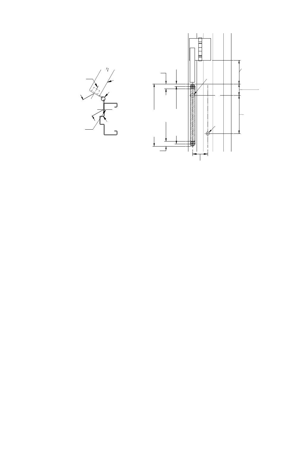
SWING GAP DISTANCE
MEASUREMENT:
EPT ~ LESS THAN 2.5" [63.5mm]
EPTL ~ GREATER THAN 2.5" [63.5mm]
(DOOR)
(HINGE)
(DOOR FRAME)
CENTERLINE REFERENCE
3/4" [19,0mm] DIAMETER
HOLE IN DOOR EDGE AND
SLOT FOR MOUNTING LEAD COVER
CENTERLINE REFERENCE
11/16" [17,5mm] DIAMETER
HOLE IN DOOR FRAME FOR
MOUNTING FLEXIBLE CABLE
7.
8
0
E
P
T
:
[1
9
8
,1
]
EP
T
L
: 1
6
.3
0
[4
1
4
,0
]
3/
4"
[
1
9
,0]
D
iam
et
e
r
1
1
/1
6"
[
1
7
,5]
D
ia
m
et
er
6
.0
0
[1
5
2
,4
] o
r
Re
c
o
m
m
e
n
d
e
d
(
M
in
imu
m
)
C
e
n
ter
Be
tw
een
B
u
tt
H
ing
es
These Two (2) Centerlines
Must Align When Door Is Closed
.495
[12,7]
1.01
[25,7]
1
0
.7
5
[2
73,
1]
1
9
.4
0 [
4
92
,8
]
1.01
[25,7]
1
2
.7
7
[32
4,
4
]
2
1
.4
3
[5
4
4
,3
]
1
1
.7
7
[29
9,
0
]
20
.4
3 [
5
18
,9
]
2.
45
[62,
2]
C
e
n
ter
li
n
e of
D
o
or
Ce
nt
e
rl
ine
of
Do
or
Figure
1
Figure
2
Wood Doors and Frames
Using a router, cut the main recess slot into the edge of the door .700” [17,8mm] deep as
explained in Figure 2 and Figure 3. Reset the router depth to .075” [1,9mm] and route the two
(2) recess flange areas for the flush mount tabs. Place the lead cover into position and mark the
location of the cable exit oblong hole and the mounting hole locations. Remove the Lead Cover
and drill the (2) two holes using a 1/8” [3,2mm] diameter drill approximately 1/2” [12,7mm]
deep. Drill the 3/4” [19,0mm] diameter hole into the door edge. Pass cable from the exit device
through the hole in the door edge. Pass the cable through the oblong hole in the Lead Cover.
Properly attach the two (2) electrical connectors at the door location. Mount the Lead Cover into
place using the two (2) #6 x 5/8” Flathead Type-A Screws provided. Locate and mark the
mounting holes for the Flexible Shield onto the door frame. Drill the 11/16” [17,5mm] diameter
hole into the door frame. Drill (2) two holes using a 1/8” [3,2mm] diameter drill approximately
1/2” [12,7mm] deep for mounting of the Flexible Shield. Pass the cable through the Flexible
Shield and apply Bezel Plate if not preassembled. Properly attach the two (2) electrical
connectors at the frame location and pass into the hole of the door frame. Mount the Flexible
Shield onto the Lead Cover using the two (2) 8-32 x 3/16” Screws and #8 Split Helical Washers
provided. Align the cable and the other end of the Flexible Shield onto the door frame and
secure using the two (2) remaining #6 x 5/8” Flathead Type-A screws provided as shown in
Figure 4.
Note: The frame side of the Flexible Shield requires the Bezel Plate
for concealing the oversize hole when mounted to the frame.
Metal Doors and Frames:
Metal doors must also have a flush surface mount installation. The door/frame manufacturer
may prepare a pre-fabricated tab for internal mounting capabilities or use the Flush Tab Brackets
provided. The cut out for the Lead Cover may be cut with a radius or square cornered as noted in
Figure 3 and on the Template provided. If field retrofit installation is being performed, route the
complete perimeter of the bracket and tab area and install the EPT/EPTL using the Flush Tab
Brackets provided. When mounting the Lead Cover, drill the mounting holes 1/8” [3,2mm] and
use the 6-32 x 3/8” Type “F” Self Tapping Screws provided. Follow the Template provided for
placement of the screw holes for the Flush Tab Brackets. Also when mounting the Flexible Shield
to the metal door frame, drill the same holes at 1/8” [3,2mm] and use the two (2) remaining 6-
32 x 3/8” Type “F” Self Tapping Screws.
Note:
Applications
containing combinations of doors or frames made of wood
or metal; follow the proper procedures related to the device as necessary.