Securitron DPA_Series User Manual
Securitron For Home
Securitron Magnalock Corp.
www.securitron.com
ASSA ABLOY, the global leader
Tel
800.624.5625
in door opening solutions
© Copyright, 2011, all rights reserved
PN# 500-15700
Page 1
Rev. C, 04/11
SECURITRON MODEL DPA-12 AND DPA-24 DOOR PROP ALARM TIMERS
INSTALLATION AND OPERATING INSTRUCTIONS
1. DESCRIPTION
The DPA series consists of a multifunction microprocessor controlled timer. Its primary function
is a sophisticated door prop alarm with numerous functions and options that permit tailoring its
alarm functions to the specific requirements of the end user. It is available as a circuit board
mounted on snap track via the part numbers: DPA-12 and DPA-24. It is also available in a
lockable steel enclosure with Sonalert and LED mounted, via the part numbers: BA-DPA-12 and
BA-DPA-24. Applications for the DPA series include doors with or without electric locks installed.
2. CIRCUIT BOARD OVERVIEW
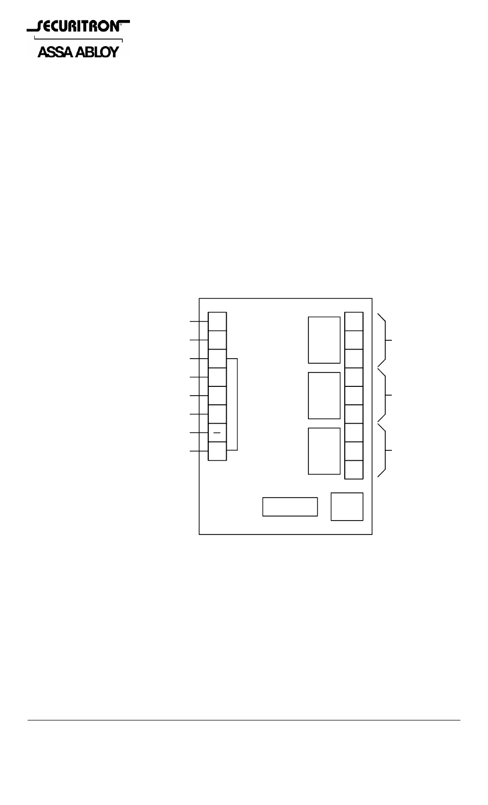
Refer to Figure 1. The DPA board consists of five logic inputs, three SPDT relay outputs and four
Dip Switches. Two terminals for polarized power input are also provided. The DPA series is
available in separate units for either 12 VDC or 24 VDC operation. Note that DC power must be
regulated or filtered. The unit will not operate on pulsating DC (transformer + bridge
rectifier). The 12 volt version draws a maximum of 100 mA and the 24 volt version draws a
maximum of 50 mA. These maximums are present when all three output relays are energized.
FIG. 1: CIRCUIT BOARD OVERVIEW
NO
NC
C1
C2
C3
+
LS
BP
FE
IN
RS
NC
NC
NO
NO
DIPS
RELAY #3
RELAY #2
RELAY #1
RESET INPUT
DOOR STATUS INPUT
LOCK STATUS INPUT
BYPASS INPUT
DURESS INPUT
0V (NEG) POWER
+V POWER
NOTE: INPUTS OPERATE
BY BEING CONNECTED TO +V
DC
NOT USED
NORMALL
ENERGIZE
3. BASIC OPERATION
The operation of the DPA occurs in four different stages. The first stage is the normal
condition. In this stage the door is closed/secure and inputs IN and LS are receiving +V. The
output relays are in their normal conditions: relays #1 and #2, deenergized and relay #3,
energized.
The next stage is the authorized condition. The door opens and time range one begins.
This range can be digitally set for 30, 60, 120 or 240 seconds. During the authorized condition,
the output relays remain in their normal states. The time period selected is the amount of time
that the user feels is acceptable for normal door use . Note that it doesn't really matter if the
door is electrically locked and employs an access control device or if the door is simply equipped
with a panic bar. The central function of the DPA is to prevent doors being propped open too
long.
RELAY#
3
NORMALLY
ENERGIZED
RELAY
#2