Securitron EPTL-SC User Manual
Page 3
PN# 500-14260
Page 3
Rev. C, 08/11
Drill a 3/4” [19,0mm] diameter hole into the door to provide routing of the wires to the device
being used. Then drill a 3/4” [19,0mm] diameter hole through the frame at the marked
locations.
Note: At this point, if the door was removed, it may be reinstalled.
Standard Wiring:
Pass the cable from the exit device being installed through the hole in the door edge.
Using a screwdriver and the four (4) 8-32 X 3/16” Phillips pan head screws and split ring lock
washers (included), assemble the flexible shield to the inside of both of the lead covers as
shown in Figure 4. Two (2) screws and washers are required at each end.
Insert the cable through the obround hole in the lead cover, feed through the flexible shield
and then out the hole of the other lead cover. Make necessary electrical connections at the
appropriate door or frame location.
Mount each of the lead covers into place using a screwdriver and two (2) of the #6 X 5/8”
Phillips flat head type “A” screws provided.
ElectroLynx® Wiring:
Insert the EL connectors at each end of the flexible shield through the obround holes inside
each lead cover.
Using a screwdriver and the four (4) 8-32 X 3/16” Phillips pan head screws and split ring lock
washers (included), assemble the flexible shield to the inside of both of the lead covers as
shown in Figure 4. Two (2) screws and washers are required at each end.
Attach the supply wiring EL connectors (from the frame) and the door device wiring EL
connectors (from the door) to the appropriate EL connectors of the EL-EPTL-SC.
As necessary, fold and tuck wiring and connectors back into the holes in door and frame.
Mount each of the lead covers into place using a screwdriver and two (2) of the #6 X 5/8”
Phillips flat head type “A” screws provided.
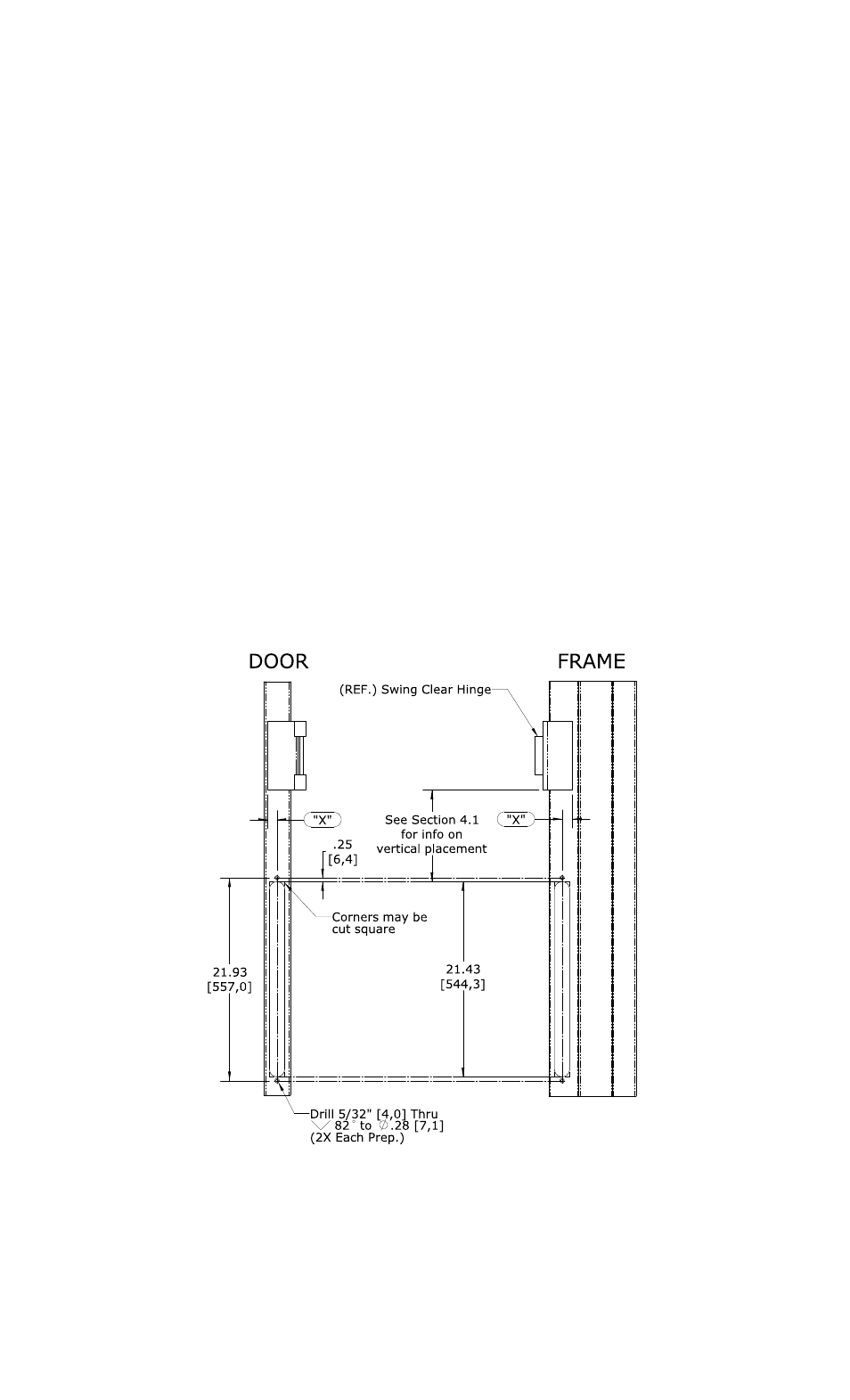
4.4 Metal Doors and Frames:
Using a router or saw, create the cutout required for the lead cover. The cutout may be cut
with a radius (as shown) or square-cornered as noted in Figure 2.
Figure 2 – Metal Door/Frame Prep.
Mark, drill and countersink the two (2) 5/32” [4,0] diameter flush tab bracket mounting holes
at each end of the cutout as shown and directed on the template.