Securitron MSS-1 User Manual
Page 4
PN# 500-16700
Page 4
Rev. D, 03/13
Next, mount the switch module. Set the leading edge of the switch to match the separation
distance printed on the label. Make sure the switch label arrow points at the magnet pack arrow
and, using the template, drill 7/64” (2.75MM) diameter holes for the #8 mounting screws and a
3/8” (9.5MM) diameter hole for the cable which will be concealed in the door frame. If you are
planning to use the tamper feature of the switch, drill a 3/32” (2.25MM) diameter hole for the
#6 tamper screw, again following the template. Be sure to use the two metal washers on
the tamper screw to yield the correct height. This installation technique produces an
attractive and high security result. A particular benefit of an inswinging door installation is that
when the door opens, it sweeps out the area under the switch. Therefore someone trying
to defeat the switch with a second magnet pack would be unable to position it in the co-planar
position because of movement of the door. Co-planar operation also precludes defeating the
switch by removing the magnet pack. As soon as the pack is off-plane an alarm will be signaled.
4. WIRING
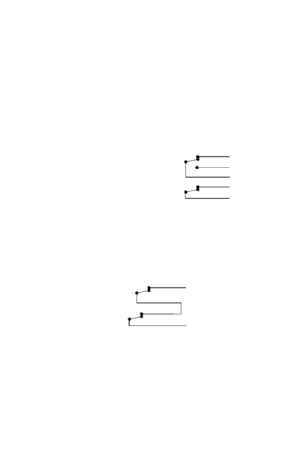
The MSS has five wires that are assigned by color as follows:
White = Common
Green = NC
Orange = NO
Red = Tamper NC
Black = Tamper NC
Because we’re using the terms normally open and normally
closed, it’s necessary to define what we mean by “normal”.
The normal condition of the MSS is when it is reporting
secure (the magnet pack is at the separation distance from
the switch module). So, for example, you’ll read a closed
circuit between White and Orange if you meter the switch
module in alarm condition (magnet is not near the switch
module) but you’ll read open if you meter it in the secure
condition.
The Red and Black tamper wires will be closed when the
tamper switch is in secure condition (depressed by the
tamper screw) and open if the tamper switch is undisturbed
(alarm condition).
Separate connection of the main switch output and the tamper output requires two alarm
points. Generally, the switch output is connected to a point which is subject to arming and
disarming depending on the time of day. The tamper contacts are connected to a 24 hour point
to raise an alarm any time the switch module is tampered with.
If two alarm points are not available
(because of wire count limitations for
example) the tamper output can be
wired in series with the switch’s NC
loop. With this connection (shown in the
drawing to the right), the circuit will
open creating an alarm condition if
either the door opens or the switch
module is tampered with while the door is closed.
Maximum contact ratings depend on the voltage put through the switch. They are 250 mA
at 12V or less and 125 mA at 24V. In special applications, the switch can accept up to 100V
but the current must be proportionately limited to a maximum 3 watt power rating (60 mA at
50V; 30 mA at 100V). The tamper circuit can handle a maximum of 1 Amp.
5. MAGNACARE
LIFETIME REPLACEMENT WARRANTY
For warranty information visit
www.securitron.com/en/site/securitron/About/MagnaCare-Warranty/
PATENT NOTE:
The products discussed in this manual are covered under US patent #5,668,533
NC
NO
COM
TAMPER NC
TAMPER NC
WHITE
BLACK
RED
GREEN
ORANGE
SCHEMATIC SHOWS SWITCH IN
SECURE CONDITION WITH TAMPER
FEATURE IN USE. CONTACTS WILL
SWITCH WHEN SWITCH ALARMS OR
TAMPER IS VIOLATED.
NC
COM
WHITE
RED
BLACK
SERIES CONNECTION OF
SWITCH AND TAMPER NC
LOOPS TO MAINTAIN BOTH
FEATURES WITH A SINGLE
ALARM POINT.
GREEN