Securitron MSS-1-RT User Manual
Page 2
PN# 500-16710
Page 2
Rev. A, 03/11
result in the alarm sounding while the switch is being tampered with. This can lead to the
person attempting to defeat the switch being identified and detained.
3. PHYSICAL INSTALLATION
The MSS can be used to monitor the opening of doors, windows, gates and barriers of all types.
The switch module is mounted on the part of the assembly that is fixed (such as a door frame)
and the magnet pack is mounted on the part of the assembly that moves (the door, for
example).
Unlike many magnetic switches, the performance of the MSS is unaffected by the type of
surface it’s mounted on. It will perform the same on steel as on wood.
In planning for mounting the MSS, note that the switch and the magnet pack have to be
oriented correctly, have to be roughly in the same plane and have to be a defined
distance apart.
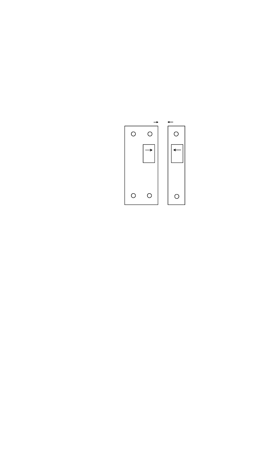
To obtain correct orientation, note the
arrows on the labels on each
component. The arrows have to
directly face each other and the ends of
the two pieces must be even, not offset.
The MSS includes a minimum and
maximum operating distance. The
unit will report secure only when the
separation distance is between this
maximum and minimum. If the magnet
pack is too close to the switch module or
too far away, the unit will alarm.
The distance between the minimum and
maximum separation points is called the
gap. The MSS provides a gap of 4/10”-1/2” (10-12.5MM). For best reliability, you want to
set the actual separation distance exactly midway in the gap. The gap will, however, vary
somewhat on each unit and the minimum distance at which the gap starts will also vary. You
can, of course determine the optimum midway separation distance by using a ruler and
Ohmmeter but as part of our QC procedure, we have checked this distance and it is printed on
the switch module label. Use this separation distance when you mount the unit.
The tamper feature on the MSS works as follows. An oval head screw (supplied) is set into the
surface which is to receive the switch module. Two metal washers are placed under the screw
head to yield the correct height. The template shows positioning of this screw. When the switch
module is installed, the tamper screw depresses the tamper switch. This closes the two wire
tamper circuit. Note that if you push the tamper switch in with a paper clip for example, you’ll
hear it click. This is not the switching point. Switching occurs much earlier in the travel so that
the height of the screw head will always move the tamper switch past its switch point but will
not bottom it out which could damage the tamper switch. Make sure, however that you place
the two metal washers under the tamper screw head and then screw it down flush
with the mounting surface. This sets up the correct height of the screw head. Note also the
fact that the switch module is tampered is undetectable and any attempt to remove the switch
module will open the tamper circuit. This circuit may be directly monitored (usually by a 24
hour circuit) or connected in series with the closed loop of the main switch output such that a
tamper violation will create the same alarm signal as if the door was opened.
3.1 CABLE PROTECTION
The Underwriter’s Laboratories standard for high security switches requires that a cable
sheathed in plastic such as the MSS-1 cable must be protected from attack by being
routed through a metal frame. This is most commonly a door frame but could also be the
frame of a gate or other opening. The mounting methods described in sections 3.2, 3.3 and 3.4
show in detail how this is to be accomplished. If your application is such that the cable
cannot be routed through a metal frame member and therefore fully protected, you
must use model MSS-1G which includes a stainless steel protective jacket for the cable (see
section 3.5). This alternative will satisfy UL’s requirements.
THE ARROWS ON THE SWITCH
AND MAGNET PACK MUST
FACE EACH OTHER AND
AND THE ENDS OF EACH
COMPONENT MUST BE
EVEN- NOT OFFSET.
SEPARATION DISTANCE IS
SPECIFICALLY NOTED FOR
EACH INDIVIDUAL PAIR.
SEPARATION DISTANCE