Securitron RLP_Series User Manual
Page 2
PN# 500-13650
Page 2
Rev. C, 05/11
Note that the "Lock Status" line which connects to red on the relay logic pack has a special
meaning. This line must supply +V to red of the relay logic pack whenever the lock is
reporting secure. It is the equivalent of the white wire on an "S" Senstat Magnalock. If your
lock status sensor is a dry closure when secure, +V from the power supply (this connection is
not shown on the drawings) must be input to lock status common with lock status NC going to
red of the relay logic pack.
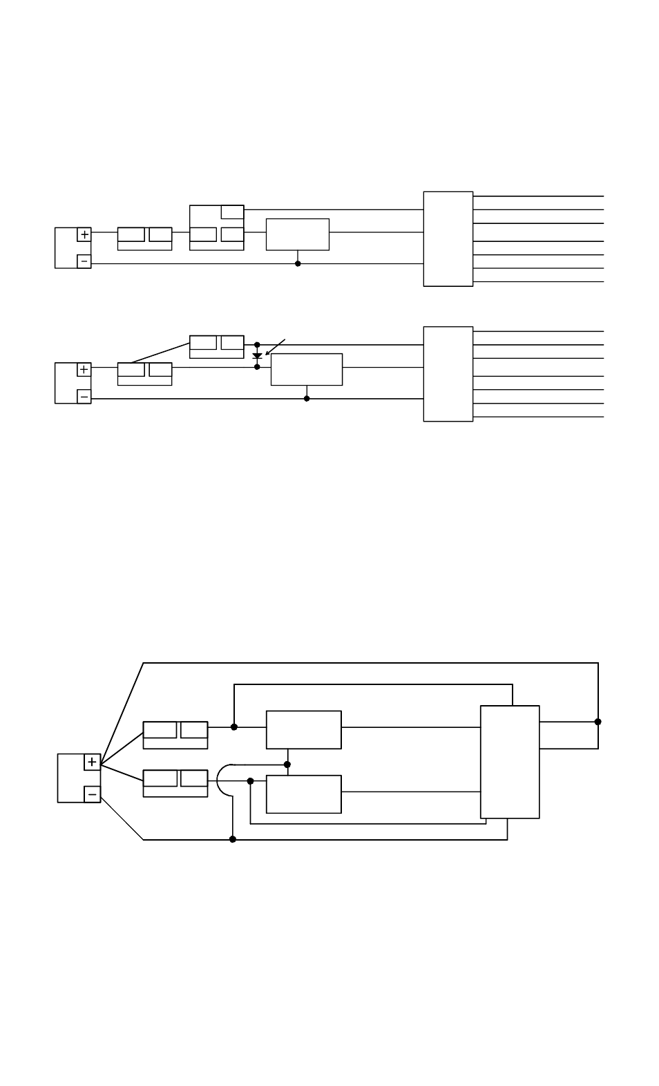
FIG. 1: ACCESS CONTROL WIRING: FAIL SAFE AND FAIL SECURE LOCKS
POWER
SUPPLY
COM
NC
NO
ACCESS
CONTROL
RELAY
EXIT SWITCH
RELAY
LOGIC
PACK
RED
BLACK
ORANGE
FAIL SAFE
FAIL SECURE
LOCK
COM
NC
LOCK
STATUS
BROWN (REX COM)
GREEN (REX NC)
YELLOW (REX NO)
POWER
SUPPLY
COM
NO
ACCESS
CONTROL
RELAY
EXIT SWITCH
RELAY
LOGIC
PACK
RED
BLACK
ORANGE
LOCK
COM
LOCK
STATUS
BROWN (REX COM)
GREEN (REX NC)
YELLOW (REX NO)
NO
DIODE
WHITE (ALARM NO)
VIOLET (ALARM NO)
BLUE (ALARM NC)
GRAY (ALARM NC)
WHITE (ALARM NO)
VIOLET (ALARM NO)
BLUE (ALARM NC)
GRAY (ALARM NC)
"LOCK STATUS" WIRE MUST OUTPUT +V WHEN LOCK IS SECURE
4. MAN TRAP INTERLOCKING
In this application, 2 electric locks with lock status sensors which are closed when secure, are
interlocked such that only one can be released at a time. The relay logic pack supplies outputs
which keep the second lock engaged when the first is not reporting secure and visa versa. The
circuit shown in the drawing below is valid for fail safe locks only when the normal
condition of the trap is locks secure. The effect of the relay logic pack is to bypass the
respective control switch when the alternate lock is not reporting secure. For definition of the
"Lock Status" wires which connect to relay logic pack red and orange, read the second
paragraph in section 3.1 above
Note that traps where the locks are normally released and traps using fail secure locks can
directly interlock via door switches or closed lock status switches and therefore do not require
the relay logic pack.
FIG 2: NORMALLY SECURE MAN TRAP INTERLOCK WITH FAIL SAFE LOCKS
RELAY
LOGIC
PACK
RED
BLACK
ORANGE
POWER
SUPPLY
COM
NC
FAIL SAFE
LOCK
LOCK
STATUS
FAIL SAFE
LOCK
LOCK
STATUS
COM
NC
1
2
BLUE
GREEN
WHITE
BROWN
SWITCH 1
SWITCH 2
"LOCK STATUS" WIRE MUST OUTPUT +V WHEN LOCK IS SECURE
5. RELAY INTERLOCK LATCH
Often it is desired that a signal condition which occurs for a period of time sets a latch that
creates a different signal which is active until reset manually regardless of whether the first
signal has continued or not. This function may be accomplished with the relay logic pack.