Securitron TSB-3 User Manual
Page 6
PN#
500-16400
Page
6
Rev.
C,
11/07
the generic products shown above with Securitron products is so simple as not to require separate
drawings. Just note that for any Securitron Magnalock, the red wire denotes the "+" input and the black
wire denotes the negative. Remember that you don't need to install the MOV with any Securitron
Magnalock. Securitron offers a wide range of different power supplies, so it is necessary to consult the
individual power supply manual to identify the DC output terminals. Then connect the power supply
outputs to the rest of the system as shown above.
FIG. 5: TSB DOUBLE BREAK WIRING
CABLE
RED (+ POWER)
BLACK (- POWER)
WHITE (RELAY COM1)
GREEN (RELAY N.C.1)
POWER SUPPLY
12-24 VOLTS
+
MOV
ACCESS CONTROL
REX INPUT
ACCESS CONTROL
LOCK CONTROL
NC CONTACTS
BLUE (RELAY COM2)
ORANGE (RELAY N.O.2)
MAGNETIC
LOCK
NC
NC
3.4 CAUTION ON USE WITH PROXIMITY CARD READERS
When a proximity card reader is used for entry and a Touch Bar is used
for egress, there is a small possibility of interference. The proximity
reader projects an electric field of considerable intensity and we have
seen rare cases where this can be picked up by the TSB. It depends
on the power of the proximity reader and the nearness of the reader
on the outside of the door to the bar on the inside. To make sure a
problem does not exist after the installation is complete, perform the
following test. Turn the bar sensitivity up as high as you can to the
point just before it is open all the time (see Section 3.6). Then, from
the outside of the door, place your hand on the reader and lean your
body against the door to see if the bar can be triggered. Coupling the
reader's energy though your body into the door, tends to increase the
bar’s sensitivity
If you find that the bar triggers from this test, there is some
interference. You have two options. It may be that the interference is
so little that when the sensor is adjusted down, there is no risk of
triggering from the outside. Experiment with this. Alternately,
Securitron has developed a simple filter circuit which will absorb the interference from the reader. See the
drawing above. This requires a 22,000 Micro Henry inductor (DigiKey part # M7223-ND, JD Miller part #
70F222AI). To install the inductor, identify the ring terminal which connects the left screw going into the
bar to the circuit board pad marked "bar". Clip this wire at the board and connect it to the left lead from
the inductor. Solder the right lead of the inductor into the pad marked "bar" on the sensor’s right side.
This pad is currently unused. Lay the inductor on top of the connector to finish.
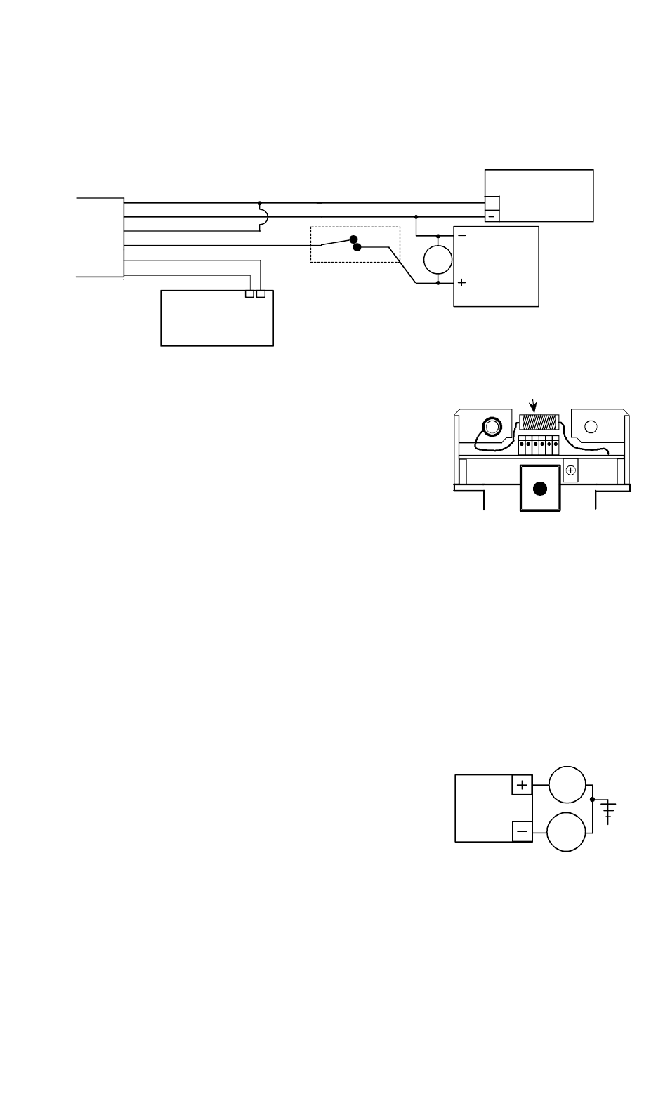
3.5 CAUTION WITH SWITCHING POWER SUPPLIES
The TSB-3 is capable of being operated by a wide variety of power supplies and does not require regulated
power but a certain type of power supply called "switching" can interfere with operation.
Most regulated power supplies are of the "linear" type. Some switching
supplies can produce line noise which will affect the TSB and rendering it
hard to adjust. If you find that a TSB is hard to adjust, check the power
supply. If it is a switcher, the power supply can be replaced with a
linear Securitron unit or addition of two capacitors generally solves the
problem. Connect one .01 mF capacitor between power supply + and
earth ground. Connect a second .01 mF capacitor between power supply
negative and earth ground. See the drawing to the left.
3.6 ADJUSTING SENSITIVITY
With wiring completed, sensor adjustment should be set. Note that the sensor board has a potentiometer
on it accessible when the bar's end cap is removed (see Figure 6). The potentiometer on the sensor will
increase sensitivity when turned clockwise and decrease it when turned counterclockwise. Turn the pot
clockwise without touching the bar with a small flat blade screwdriver until you hear the relay click off.
In this condition, sensitivity is so high that the bar is “sensing” all of the time. Slowly rotate the pot
counter-clockwise until you hear the relay click off and then another 15 degrees counter-clockwise. This is
SWITCHING
POWER
SUPPLY
.01 mF
.01 mF
EARTH GROUND
INDUCTOR
SOLDER ONE END OF INDUCTOR
INTO PAD MARKED "BAR" ON RIGHT
SIDE OF SENSOR. CLIP WIRE
FROM RING TERMINAL, REMOVING
IT FROM SENSOR AND CONNECT
IT TO OTHER END OF INDUCTOR.