Connecting to assa abloy aperio, Products aperio, Products with the dkc, an ah20 aperio – Securitron DKC User Manual
Page 6: Hub. aperio
PN# 500-33510
Page 6
Rev. A, 06/13
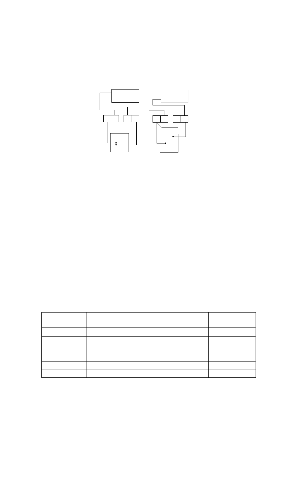
Adding Other Lock Control Switches
Sometimes other control switches are needed that are not appropriate for the REX input, as use
of this input triggers the timed release capability of the DKC. A typical example would be a
switch located centrally which would release the lock in response to an intercom call for
example. If the lock is fail safe, the switch will need to break power to the lock and if it is fail
secure, the switch will need to send power to the lock. Figure 5
shows how to add external
contacts for non-timed remote release of the lock for both lock types.
COM
ADDING EXTERNAL CONTACTS FOR FAIL SAFE AND FAIL SECURE LOCKS
Figure 5
NC
FAIL SAFE LOCK
FOR NON‐TIMED REMOTE
RELEASE OF FAIL SAFE LOCK,
PLACE NC CONTACTS IN
CIRCUIT AS SHOWN
DC
+
DC
‐
+
‐
NO
NC
COM
FOR NON‐TIMED REMOTE
RELEASE OF FAIL SECURE LOCK,
PLACE NO CONTACTS IN
CIRCUIT AS SHOWN
COM
NO
FAIL SECURE
LOCK
DC
+
DC
‐
+
COM
‐
Connecting to ASSA ABLOY Aperio
TM
Products
Aperio
TM
technology is a global wireless platform that reduces the cost and inconvenience of
traditional access control – without the hassle of complex site surveys. It utilizes local wireless
communication between the lock and a communications hub to connect to an online electronic
access control system. This offers facilities an easy, affordable way to expand the reach of
existing access control systems and secure additional openings.
When using Aperio
TM
products with the DKC, an AH20 Aperio
TM
Wiegand Hub must be used.
Please note that the green/red light logic must be set to ‘Reverse’. Additionally the ‘Aperio hub’
option button must be selected on the ‘Keypad/Aperio Hub’ option for the associated door. These
options are selected in the Door Options tab in the DKC Programming Tool. Please note that
Passage mode CANNOT be used with an Aperio
TM
hub. Aperio
TM
products conform to higher
security requirements that do not allow passage mode to be used.
Wiring the Aperio
TM
hub to the DKC is shown in Table 3 and Figure 6.
DKC
Terminal
DKC Wiring Reference
Suggested
Wire Color
Aperio Hub
Terminal
+12V
Positive DC supply lead
Red
8-24V DC
D0
Wiegand data zero
Green
D0
D1
Wiegand data one
White
D1
LED-G Green
LED
Orange GREEN
LED-R Red
LED
Brown RED
(-) Ground
Black
GND
Table 3: Minimum Wiring Terminal Connections from DKC to Aperio hub