Securitron EEB3N User Manual
Securitron For Home
Securitron Magnalock Corp.
www.securitron.com
ASSA ABLOY, the global leader
Tel
800.624.5625
in door opening solutions
© Copyright, 2011, all rights reserved
PN# 500-12600
Page 1
Rev. E, 06/11
SECURITRON EEB2, EEB3N EXIT BUTTON WITH INTEGRATED TIMER
INSTALLATION AND OPERATING INSTRUCTIONS
1. DESCRIPTION
The model EEB2: 2" square, exit button, mounted on a S.S. single gang keyplate. The model EEB3N:
rectangular exit button, mounted on a 1-3/4” S.S. narrow stile keyplate. The EEB2 and EEB3N have a 3
Amp switching capacity and a timer set for 30 seconds. These units are intended only for release of a
magnetic lock from the inside of a door. When the button is pressed, the lock releases for 30
seconds. If pressed again during the 30 second lock release period, the unit will “retrigger” starting a
new 30 second lock release period. These buttons are specifically intended for installation on access
controlled egress doors as described in the BOCA code. A motion detector, such as Securitron’s model
XMS, is the primary means of releasing a magnetic lock on the door. The button is employed as a backup
means of releasing the lock in case of a problem with the motion detector. Note that the exact time will
vary with temperature but it will not be less than 30 seconds.
2. INSTALLATION
The EEB2 comes with a mounting device. The EEB3N has no mounting device and is intended for direct
mounting on a narrow stile aluminum door frame. The frame must be routed out sufficiently to
accommodate the EEB3N components.
3. WIRING
The unit will operate on 12VDC or 24VDC. Full wave rectified DC (transformer + bridge rectifier) is
acceptable. It draws no current when at rest and 28mA @ 12V or 38mA @ 24V when releasing the lock.
The black box that is affixed to the rear of the keyplate houses the timing electronics. Identify the hole in
the side of the box with a plastic jumper block partly protruding from it.
Factory shipped with jumper installed. Jumper in place = 12V. If removed = 24V. NOTE: If the
unit is operated on 24V with the jumper in place, it can be damaged. The unit must operate on
the same power supply that operates the magnetic lock.
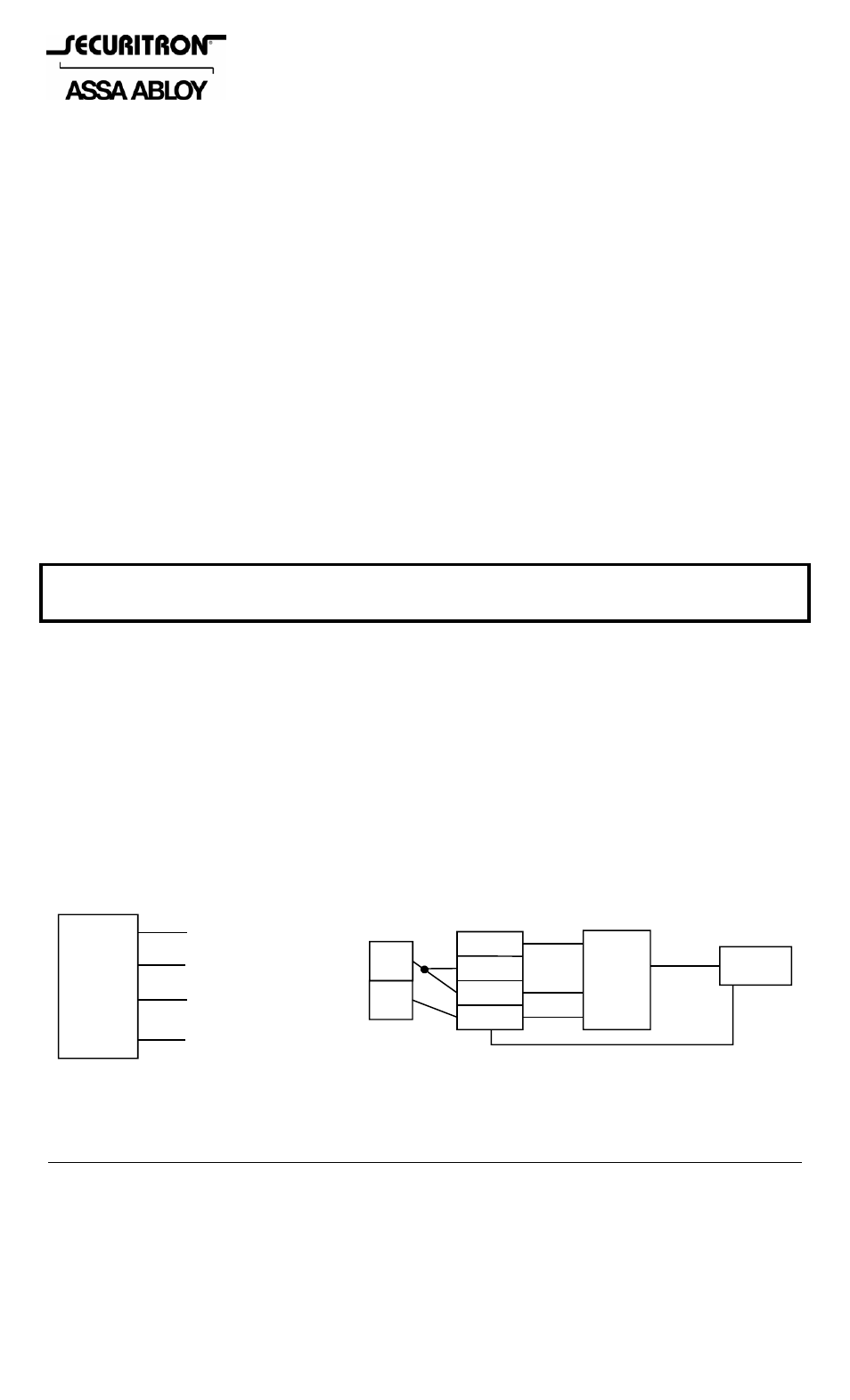
Four flying leads constitute the connection points for the unit. Two are for the application of constant
power and two are for control of the magnetic lock. Figure 1 shows the color coded identification of the
wires and a typical wiring diagram showing a power supply, motion detector, push button and Magnalock
so as to comply with the BOCA code for access controlled egress doors.
Note: Both the push button contacts and the internal timer relay contacts are in series with the white and
green wires. This “double break” wiring provides additional safety if for any reason, the timer
electronics failed, pressing the button would still cut power to the lock for as long as the button is held in.
The white and green wires do not constitute dry NC contacts. To operate properly, they must only
be connected as shown in Figure 1: The white wire goes to a source of +V and the green wire goes to the
positive input wire of a magnetic lock. Note that another switching device such as a motion detector can
be put between the white wire and the source of +V (as is shown in Figure 1). Figure 2 shows the internal
schematic of the push button contacts and timer which helps clarify the unusual wiring method needed to
maintain double break safety.
FIG 1: WIRE IDENTIFICATION AND TYPICAL HOOKUP
RED
BLACK
GREEN
WHITE
EEB2
OR
EEB3N
+12V OR +24V
0V (DC NEG)
TO LOCK “+” WIRE
TO +V
+
_
POWER
SUPPLY
XMS
DEVICE
IN+
+
_
WHITE
RED
BLACK
EEB2
OR
EEB3N
GRE
E
N
R
E
D
MAGNA-
LOCK
BLACK
NOTE:
Positive input voltage on the white wire
must be from same power source that the
red & black wires are connected to.