Securitron PB3AN User Manual
Page 2
PN# 500-15100
Page 2
Rev. D, 02/12
Flat section
Flat section
LED Back View
The red indicator draws 20 mA at either voltage. For replacement: the red indicator LED is
Securitron’s part number 700-10095 the switch LEDs are listed in the table below.
Switch Green LED
030-11000
Switch Red LED
030-11030
4. WIRING
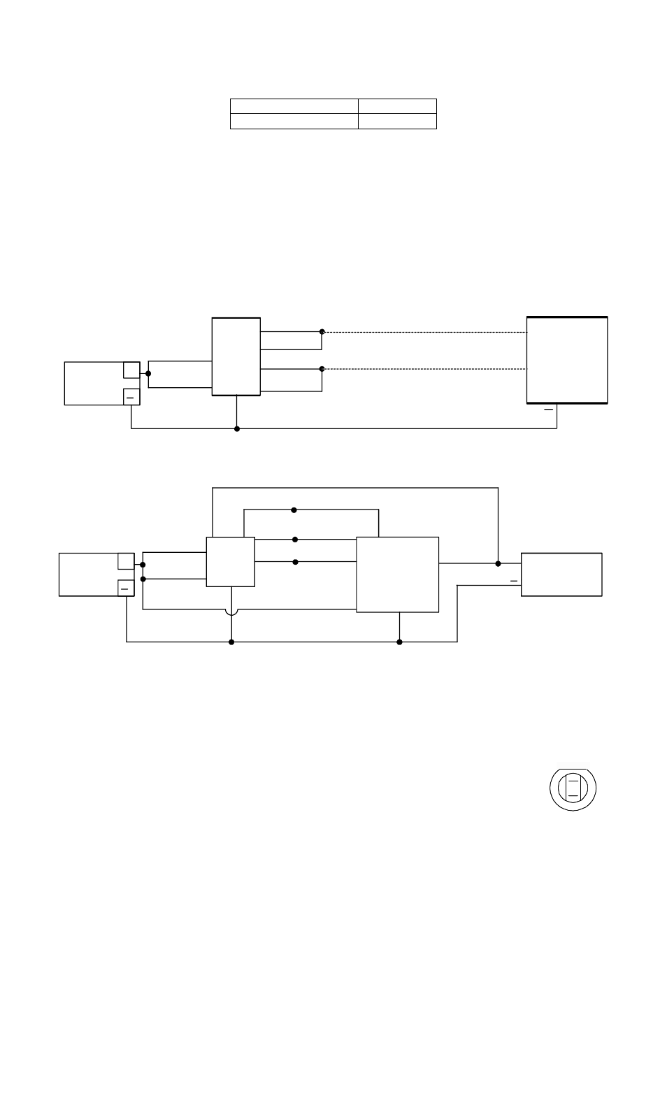
The drawings below show two common applications. The first shows momentary release of a fail
safe or fail secure electric lock. The PB3 indicators are connected so that the switch LED is
normally on. When the button is pressed, releasing the lock, the switch LED turns off and the
Keyplate indicator comes on. The second drawing shows timed release of a fail safe electric lock
using the PB3 and Securitron's TimeMate. Momentarily pressing the button will release the lock
for the amount of time set on the TimeMate. The Switch LED will switch off and the keyplate
LED illuminates during the lock release period. The wiring is also done in double break fashion
so that even if the timer fails, the button will still be able to momentarily release the lock. This
is for added safety.
POWER
SUPPLY
TIMEMATE
+
YELLOW
RED
WHITE
BLACK
D.C. LOCK
FAIL SAFE
GREEN
PB3
+
RED/WHT
BLUE/WHT
BLUE
RED
BLACK
BLUE
YE
LL
O
W
GREE
N
POWER
SUPPLY
+
D.C. LOCK
ELECTRIC
PB3
+
RED/WHT
BLUE/WHT
BLUE
RED
BLACK
+
GREEN
YELLOW
IF FAIL SAFE
IF FAIL SECURE
MOMENTARY RELEASE OF FAIL SAFE OR FAIL SECURE ELECTRIC LOCK
TIMED DOUBLE BREAK RELEASE OF FAIL SAFE LOCK
5. ALTERNATE LENS CHANGING
The pushbutton is factory shipped with a green lens set installed and an optional red lens set.
Changing to the Red set is simple
1) While holding the keyplate grasp the top and bottom of the lens and pull straight out from
the keyplate.
2) To remove LED use a fine-nosed pliers and grasp LED by the sides and
pull straight out.
3) To replace the LED. Look at the back of LED and locate the flat section
on the LED circumference. The flat section will go up when inserting the
LED into the switch. With fine-nosed pliers grasp the edges of the LED
from the front side of the LED, lineup the LED terminals with the socket
in the switch and gently push the LED into the switch.
4) Place the lens over the switch face confirm that the text on the lens is right reading to the
keyplate and push down completely until it snaps into place. Depress lens several time to
ensure smooth operation and that the lens is not binding.