Securitron PB4 User Manual
Securitron For Home
Securitron Magnalock Corp.
Tel 775.355.5625
550 Vista Boulevard
Fax 775.355.5633
Sparks, NV 89434
www.securitron.com
© Copyright, 2008, all rights reserved
PN# 500-16100
Page
1
Rev. C, 2/08
ASSA ABLOY, the global leader
in door opening solutions
SECURITRON PB4 SERIES EXIT BUTTON
INSTALLATION AND OPERATING INSTRUCTIONS
1. DESCRIPTION
The model PB4 series exit button is an all steel unit specially designed to resist vandalism. The
button cannot be removed or tampered with from the outside. It is designed to resist shocks
such as hammer blows. A bi-color LED is included. The unit is available in different versions.
Part number PB4 calls out a momentary spring loaded button on a single gang stainless steel
plate with 4 Amp rated SPDT contacts. Adding the suffix "N" identifies the same unit on a 1 3/4"
wide narrow stile plate. Adding the suffix "A" changes the push button switch to alternate action
(push on/push off). Finally, adding the suffix "2" upgrades the contacts to DPDT. Securitron
part numbers for replacement switch elements are: 100-13500 (momentary SPDT), 100-13700
(momentary DPDT) and 100-13800 (alternate DPDT).
The PB4 can be used for momentary release of fail safe or fail secure electric locks. If interfaced
with a release hold timer, such as Securitron's TimeMate, it can provide for timed release of
electric locks. It may also be used to input a REX (request to exit) signal to a card reader
system. We recommend that the local building or fire safety authority be consulted prior to
using exit buttons for door egress. They may require a "no special knowledge" exit device such
as Securitron's Touch Sense Bar.
2. INSTALLATION
The PB4 comes with a retrofit backbox and color coded hookup wires installed. A choice of
fasteners are also supplied. The installer may elect to use standard 6-32 slot screws or the 6-32
spanner head screws, which provide a degree of tamper proofing. The backbox (Securitron part
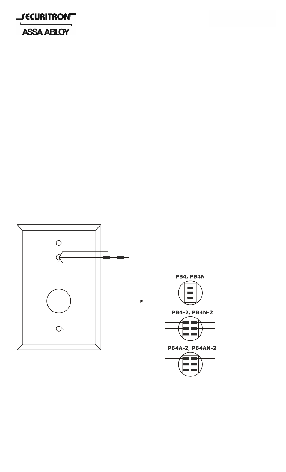
number 560-10200). The drawing below shows identification of the unit's connection points.
REAR OF UNIT SHOWN
RED LED WIRE
GREEN LED WIRE
BLACK LED WIRE (NOTE RESISTORS)
WHITE (COM2)
RED (NC2)
BLUE (NO2)
WHITE (COM2)
RED (NC)
BLUE (NO)
WHITE (COM)
BLUE (NO1)
WHITE (COM1)
RED (NC1)
WHITE (COM1)
BLUE (NO1)
BI-COLOR
LED
WIRE IDENTIFICATION
BOTH LED COLORS OPERATE ON 24VDC
AS DELIVERED. REMOVE THE OUTER
RESISTOR TO OBTAIN 12 VOLT OPERATION
RED (NC2)
BLUE (NO2)
RED (NC1)