Securitron PB5 User Manual
Page 2
PN# 500-23150
Page 2
Rev. C, 05/11
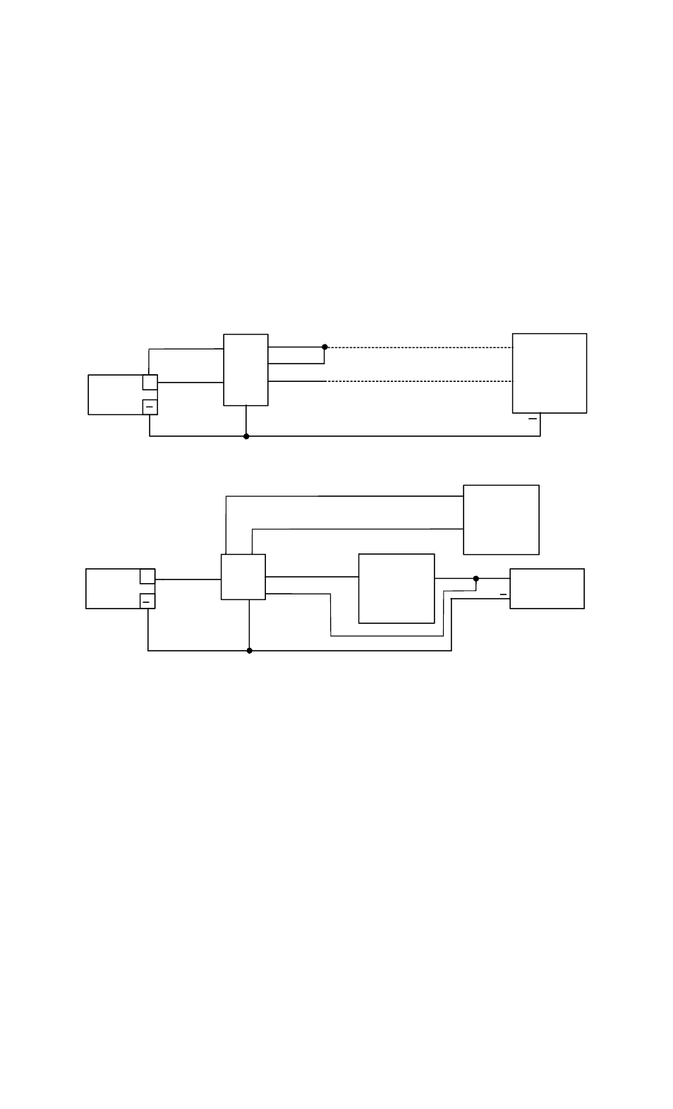
4. WIRING
The drawings below show two common applications. The first shows momentary release of a fail
safe or fail secure electric lock. The PB5 indicator is connected so that the switch LED is
normally on (which helps guide a person to the push button). When the button is pressed,
releasing the lock, the switch LED turns off. The second drawing shows interface of the PB5 with
an access control system such that a fail safe lock (generally a magnetic lock) is released for the
amount of time programmed into the system in safe, double break fashion. This application
uses both poles of the PB5. The NC contacts of the PB5 are connected in series with the NC
contacts of the access control system’s lock control relay and the NO contacts of the PB5E
connect to the REX input terminals of the access control system such that when the button is
pressed, the access control system will operate its relay thereby releasing the lock and allowing
egress. But if the access control system experiences an electronic failure, the PB5E contacts will
still directly release the fail safe lock for as long as the button is held pressed.
Note: for special applications, unwired contacts NO1 and NC2 can be connected for full DPDT
switch operation. You will see the unwired spade terminals on each contact block.
POWER
SUPPLY
+
D.C. LOCK
ELECTRIC
PB5
+
WHITE/RED
BLUE
RED
BLACK
+
GREEN
IF FAIL SAFE
IF FAIL SECURE
MOMENTARY RELEASE OF FAIL SAFE OR FAIL SECURE ELECTRIC LOCK
WHITE/BLUE
POWER
SUPPLY
+
COM
D.C. LOCK
FAIL SAFE
NC
PB5
+
ACCESS
SYSTEM
RELAY
ACCESS
SYSTEM
REX INPUT
TIMED DOUBLE BREAK: FAIL SAFE LOCK USED WITH ACCESS SYSTEM
WHITE/RED
RED
W
H
IT
E/
BL
U
E
BL
U
E
GREEN
BLACK
4. ALTERNATE LENS CHANGING
The pushbutton is factory shipped with the red lens set installed and two lens/insert options.
Changing to the other lens sets is simple.
1) Grasp keyplate and turn over. From the back rotate the white contact block of the switch
counter-clockwise to the 11 o’clock position and pull straight back to remove the contact
block.
2) With a slender smooth ended object such as a marker pen, slide it inside the switch body.
With the object inserted in the switch up against the lens, place the object on a smooth
surface with the keyplate on top, and tap the keyplate up and down on the object to pop
the lens off. Remove the lens and insert.
3) Turn the keyplate over and place the new insert onto front of switch, confirm that the text
on the insert is correct reading to the keyplate and place the matching colour lens on top of
the insert and compress around all edges of the lens until it snaps in place. Depress lens
several more times to ensure smooth operation and that the lens is not binding.
4) With the terminals upward insert the contact block back into the back of the switch at the
11 o’clock position and rotate clockwise until it stops straight up and down.