Installation instructions, Frame preparation, Mm15 maglock mounting basics – Securitron MM15 User Manual
Page 2
4
In each mounting location, drill a 3/8” hole in the header and
install Blind Nuts, using the supplied hex wrench. Refer to
Blind Nut installation instructions in the mounting hardware
kit.
Note: In reinforced steel frames, it is permissible to drill
5
If not using conduit, drill one 9/16” (or 3/8” minimum) wire feed
hole in the door frame.
6
Replace the mounting plate and filler plate, then secure with pan
head screws using thread lock.
6
Additional screws may be installed for added stability and strength
in any of the alternate holes.
Frame Preparation
Frames need to be marked for drilling using the mounting plate as a
template. Doors need to be marked for drilling using the plastic armature
template. All measurements should be made with the door in the fully
closed position.
To ensure the proper location of the maglock and armature for successful
mounting, adjust the MM15 to clear other hardware or door and frame
features that would interfere with the installation.
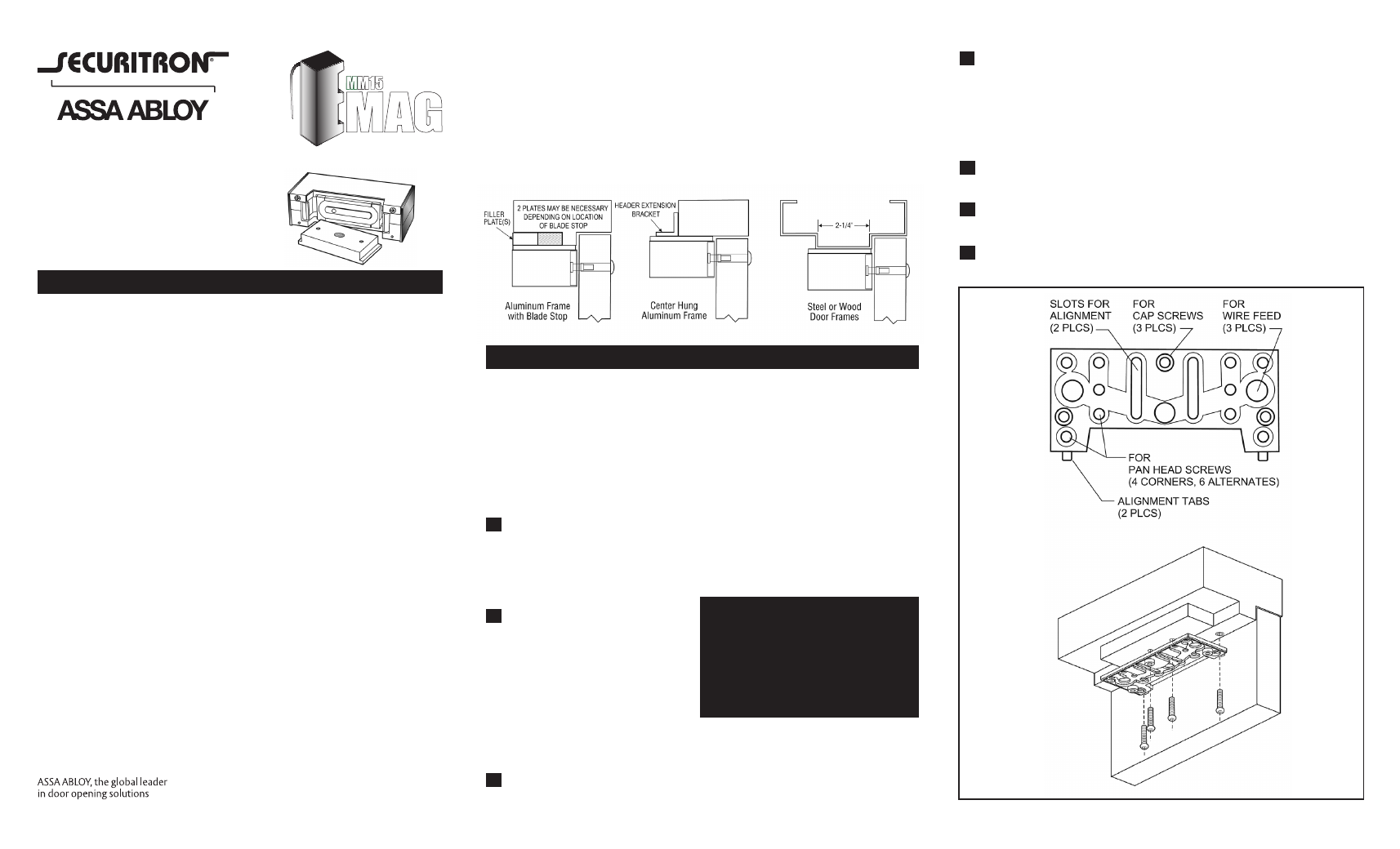
1
Place the filler plate on the
mounting plate. The filler
plate should be aligned with
the back edge and sides of
the mounting plate.
2
With the door fully closed,
locate the mounting plate and
the filler plate to the header
with the alignment tabs resting
on the face of the door. Using
the predrilled holes in the center
of the filler plate and two of the
furthest forward corner holes,
mark four holes for mounting
the two plates to the header.
3
If not using conduit, mark one
of the wire feed hole locations.
Installation shown with use
of filler plate. Mounting will
differ for other applications.
WARNING:
This device is capable of holding
4000 lbs. It is the responsibility of
the installer to provide adequate
strength to prevent screw pullout
or collapse of the frame or header.
MM15 Maglock Mounting Basics
Maglocks are used in a wide variety of applications; therefore it is
important to inspect the door frame area for proper placement of the
device. For optimum performance, the mounting surface should be
strong enough so that the full holding strength of the MM15 is utilized.
Different door frame configurations require specific fastening methods.
A filler plate or header extension bracket is often needed to properly
support the MM15. Steel blind nuts are the preferred method of
mounting in steel and aluminum frame construction, although drilling
and tapping is acceptable in reinforced hollow metal frames. A
minimum of four blind nuts are required to provide adequate strength.
For standard applications, the electro-magnet should be mounted
firmly to the underside of the header in the corner farthest away
from the hinges. The armature mounts to the face of the door with
special hardware, which allows for proper floating action. This action
is very important in assuring total mating of the armature with the
face of the electro-magnet.
Handle all electro-magnetic locks and armature plates carefully. Any
damage to the mating surfaces may significantly reduce holding
efficiency.
Site Survey
When used with frames with an integral jamb or with narrow frames
that do not fully support the MM15, use the appropriate filler plate or
header extension bracket to adequately support the base of the MM15.
A Z-Bracket is required when installing the MM15 on in-swinging
door. The Z-Bracket installation instructions are included in the MM15
Z-Bracket Kit.
This product must be installed
according to all applicable building
and life safety codes.
Installation Instructions
MM15-01 Rev. C
Page 1
Aluminum Door Systems:
Door frames with blade-type/narrow stops will require a filler plate. The
height of the stop is needed when ordering filler plates. Narrow frame
sections and centerhung doors require an angle bracket to support the
MM15.
Steel/Wood Door Frames:
For adequate support, a door with stops less than 2-1/4” wide should
be fitted with a filler plate.