Securitron SMLS_SMSS User Manual
Page 2
PN# 500-12400
Page 2
Rev. D, 03/11
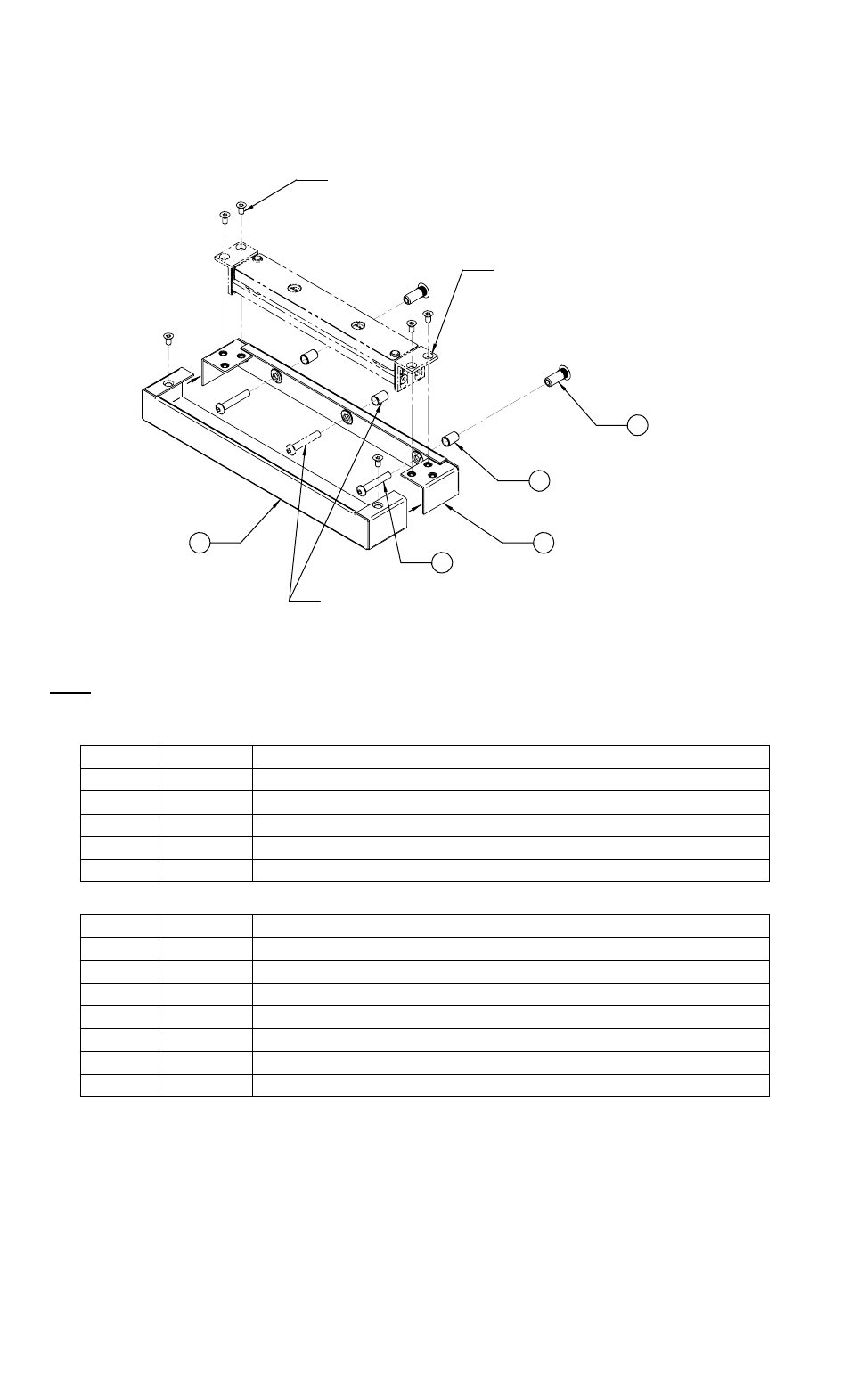
Strike Armature Installation using SMSS/SMSSM
Figure 2 below is an exploded illustration of the general strike armature mounting
configuration available using the hardware provided:
2
1
4
3
(6) 10-32 UNF X 3/8" LONG
FLAT HEAD SOCKET SCREWS
SUPPLIED WITH SAM LOCK OR
METRIC (SMSSM) VERSION OF
STRIKE MOUNT
(REFERENCE) SAM STRIKE
ARMATURE - NOT INCLUDED
5
(OPTIONAL) - CENTER HOLE OF
BRACKET MAY ALSO BE USED
FOR MOUNTING IF NECESSARY
Figure 2
Note: The items represented by the phantom/dashed lines are for reference only – the SAM
Strike Armature and its associated hardware are NOT included with this product.
U.S. Standard:
ITEM QTY
DESCRIPTION
1
1
Lock/Strike Mounting Bracket
2 1
Lock/Strike
Bracket
Cover
3
3
1/4-20 UNC X 1-1/2” Long Button Head Socket Cap Screw
4
2
1/4-20 UNC Blind Nut, 1-Piece, Steel
5
2
Sex Bolt, 1/4-20 UNC X 1” Long, Steel
Metric:
ITEM QTY
DESCRIPTION
1
1
Lock/Strike Mounting Bracket
2 1
Lock/Strike
Bracket
Cover
3
3
M6-1.0 X 40MM Long Button Head Socket Cap Screw
4
2
M6-1.0 Blind Nut, 1-Piece, Steel
5
2
Sex Bolt, M6-1.0 X 25MM Long, Steel
6
6
10-32 UNF X 3/8” Long Flat Head Socket Screw
7
1
Hex Wrench, 1/8”