Robot waterbase applicator - maintenance, Fluid tube repair / replace, Fluid tube reassembly – Ransburg Evolver Water Applicator 78863-90, 78863-60 User Manual
Page 36
32
Robot Waterbase Applicator - Maintenance
Figure 12: Solvent Resistant O-Ring Kit
1. To remove and replace low voltage cable, refer
to Figure 18. Remove applicator from robot wrist.
(See Figure 7.)
2. Remove screw [1] from position shown. Insert
3/16" wrench to remove set screw [2]. The cable may
now be removed.
3. To re-install, pull the cable through the robot
arm. Install in the low voltage cable hole. Align the
timing marks as shown in Figure 19.
4. Tighten the set screw [2] until tight. Re-install
the screw into position shown.
Fluid Tube Repair / Replace
1. Remove the atomizer from the robot. (Refer to
Figure 7.)
8. Pull out the tube straight out of the fitting, being
carefull not to break the ferrules.
9. Carefully slide the ferrules and nuts off the old
fluid lines for re-use.
10. Cut the existing tube a minimum of 2 ft. back from
the end where the barbed fittings were located.
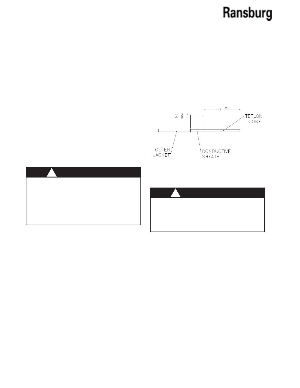
11. Cut away the jacket and coductive sheath ac-
cording to Figure 19.
>
If the inner of the fluid line is nicked in any
way, you must start over at Step 10. Any nicks
will cause premature failure or high voltage pin
holing after installation.
W A R N I N G
!
>
Depressurize, clean, and blow all fluid lines
dry.
>
Insure voltage is turned OFF.
>
Insure robot is locked-out.
W A R N I N G
!
2. Remove (6) screws that retain the tubing
bundle to the robot wrist.
3. Disconnect all cable and tubing connections.
4. Clamp the robot plate in a soft jawed vice to prevent
any scratching or defacing of the plate.
5. Remove all pilot lines around the fluid dump
line.
6. Remove the nut from the paint and dump line
fittings.
7. Cut off the end of the tube where the barbed
fittings are located and discard the barbed fittings
Figure 19: Fluid Hose Cutback Diagram
Fluid Tube Reassembly
12. Apply a thin film of SSL-11 petroleum jelly on the
conductive sheath to aid installlation of ferrule.
13. Slide nut over the tube. Carefully, slide the fer-
rule over the conductive sheath, leaving no raised
edges. Insure the outer jacket of the tube bottoms
out inside the ferrule.
14. Apply anti sieze to the fitting threads. Slide the
tube inside the fitting, until the ferrule shoulders
against the back of the fitting. Carefully slide the nut
over the ferrule and tighten.
AA-03-01.1