Robot manifold assembly – Ransburg Evolver Water Applicator 78863-90, 78863-60 User Manual
Page 17
Robot Waterbase Applicator - Installation
13
ROBOT MANIFOLD ASSEMBLY
The tubing, hose, and low voltage cable come
bundled from the factory. Pull the bundle through
the robot spacer plate and robot wrist carefully to
prevent any cuts on the cable or hoses. Connect
each signal line as required per signal legend:
AP
Air Purge (Blue color)
DP
Dump Pilot (Red color)
TP
Trigger Pilot (Green color)
A
Atomizer Air (Natural color)
F
Fan Air (Black color)
Connect "Paint In" and "Dump Out" line (shielded
hose) to their proper respective connections. Im-
proper connection of these lines could cause damage
to the applicator.
>
"Paint In" line is 3/16" I.D., "Dump Out"
line is 1/4" I.D.
NOTE
Once all connections have been verified, install the
robot spacer plate to the robot wrist using 6 screws
(not provided).
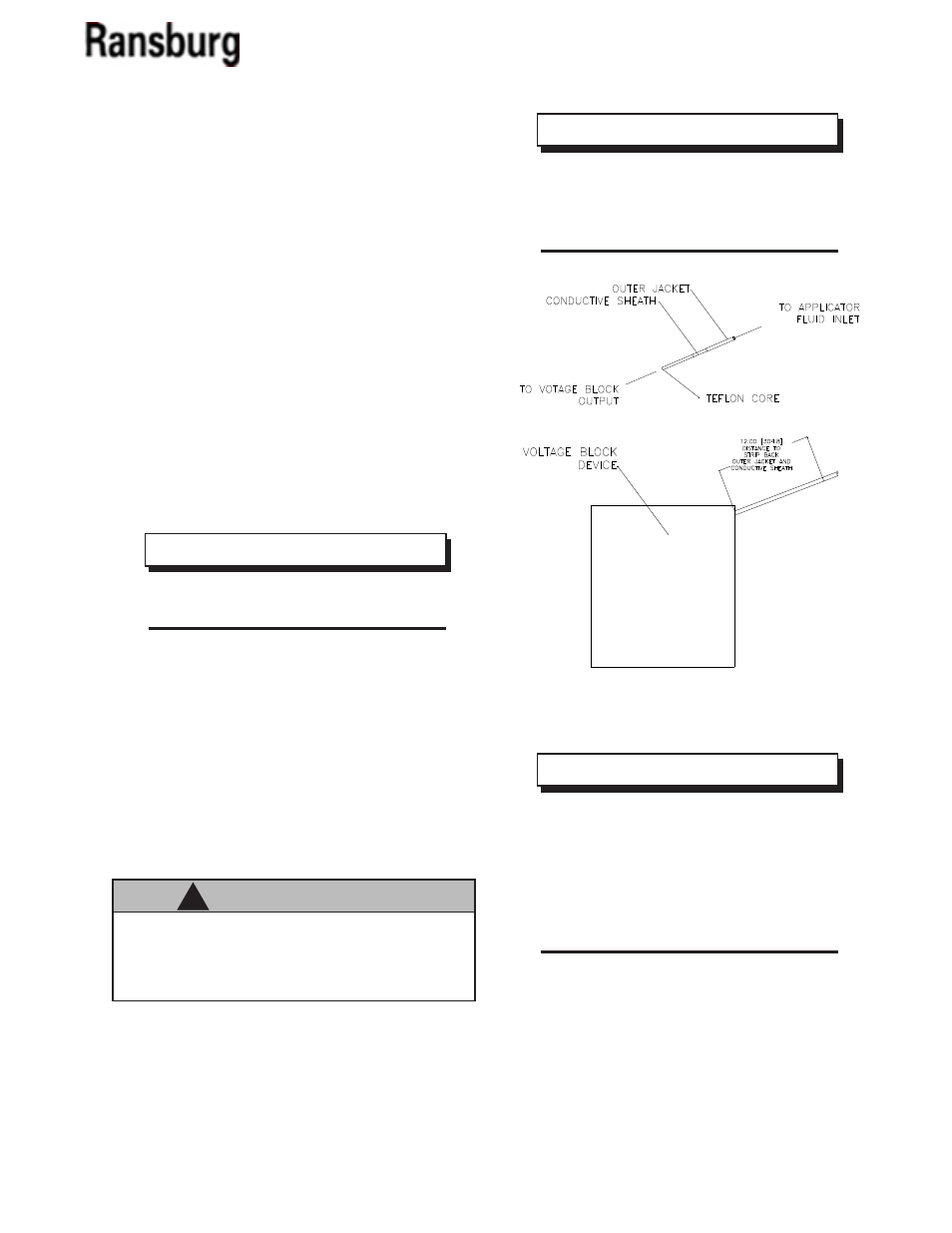
Insure the shielded hose for the paint in line has
stripped back the outer jacket and conductive sheath
at least 12" from the exit of the voltage block devise.
(See Figure 5)
>
Failure to strip back the shielded hose will
increase current draw and lower tip voltage
reducing efficiency of the applicator.
NOTE
>
Try to keep the shielded 3/16" I.D. "Paint
In" line and the 1/4" I.D. "Dump Out" line as
long as possible. If these hoses should pin-
hole, this will allow a cut-off of the pinhole
section. Strip back and re-assemble rather
than replacing the entire hose.
NOTE
>
Do Not nick or cut the inner paint line
hose. This will cause premature failure of the
hose.
C A U T I O N
!
Figure 5: Shielded Hose Stripbacks Diagram
AA-03-01.1