Operating instructions – General Tools and Instruments CMR35 User Manual
Page 7
OPERATING INSTRUCTIONS
MAKING BASIC MEASUREMENTS WITH THE TRANSMITTER
As you make measurements, be aware that pressing the HOLD button on the transmitter
(callout 6 of Fig. 1) temporarily stores (memorizes) the displayed reading. This feature
comes in handy when making measurements under low-light conditions or in tight
spaces (under counters, in crawl spaces or attics, or inside electrical panels) where the
display is out of sight. In these cases, press the HOLD button to freeze the reading
(causing the letters “D-H” to appear on the top line of the display). Then move the
transmitter to where its display can be read more easily. To release the held reading,
press the HOLD button again.
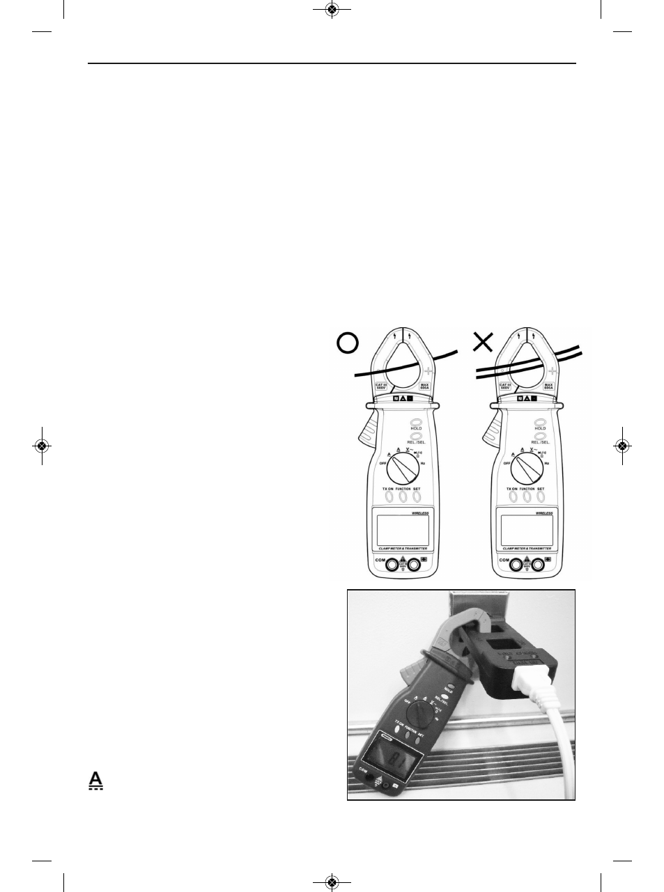
MEASURING CURRENT
To measure the AC current flow through a conductor, move the function switch to the
A
~ position, squeeze the clamp trigger to open the clamp, and place one conductor only
in the center of the clamp’s jaws, as shown in the following figure. Read the value once
it stabilizes.
It is good practice to measure the
current carried by the “hot” line
(usually a black or red wire).
Measurements of current through
the return or neutral conductor
(usually a white wire) may be
misleading because the return may
be used by other circuits.
To measure the current drawn by an
appliance with a fixed power cord,
General recommends using an
industry-standard AC line splitter, as
shown in the following figure. To
purchase an AC line splitter from
General, see p. 31.
In AC current measurement mode, the
CMR35T selects a 0 to 400A measurement
range unless the input is greater than 400A.
In this case, the unit automatically switches
to a full-scale range of 0 to 600A.
When you have finished making measure -
ments, move the function switch to the
OFF position.
To measure the DC current flow through a
conductor, move the function switch to the
position, squeeze the clamp trigger to
open the clamp, and place one conductor
only in the center of the clamp, as shown in the earlier figure.
7
BLACK OR
RED (HOT)
WIRE
CMR35 Manual FINAL4_020911:awb 2/9/11 11:54 AM Page 7