Product overview – General Tools and Instruments CMR35 User Manual
Page 5
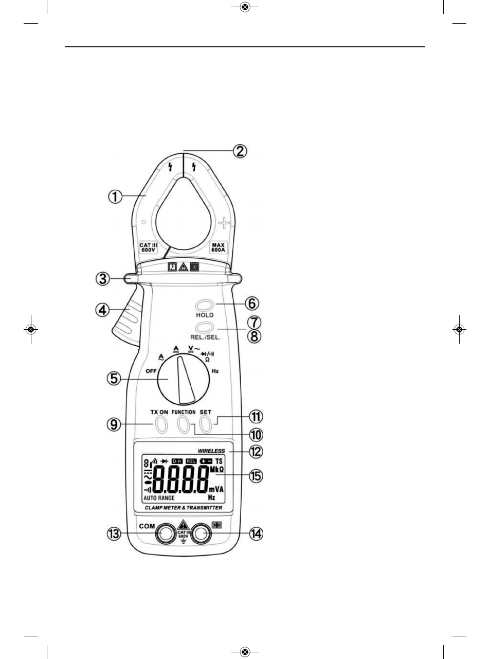
PRODUCT OVERVIEW
Before using the transmitter and receiver together, learn how to make some basic
measurements using the transmitter unit alone. To begin, familiarize yourself with
Figures 1 and 2. Fig. 1 shows the transmitter unit’s controls, indicators and jacks. Fig. 2
shows the symbols used by the transmitter’s liquid-crystal display, as well as their
positions.
ቢ Clamp
ባ Clamp tips/opening
ቤ Guard ring
ብ Clamp trigger
ቦ Function switch
ቧ HOLD button
ቨ ቩ REL./SEL. button
ቪ TX ON button
ቫ FUNCTION button
ቭ SET button
ቮ Nameplate
ቯ COM (negative or ground)
input jack
ተ {
+
(positive) input jack
ቱ Liquid-crystal display
Fig. 1. The transmitter’s controls, indicators and jacks
5
CMR35 Manual FINAL4_020911:awb 2/9/11 11:54 AM Page 5
See also other documents in the category General Tools and Instruments Tools:
- 119 (1 page)
- 146 (2 pages)
- 1478 (1 page)
- 147 (1 page)
- 80560 (1 page)
- 840 Pro Doweling Kit (36 pages)
- 840 use of Dowel Centers (4 pages)
- 841 (8 pages)
- 849 (2 pages)
- 850 (2 pages)
- 860 v.1 (16 pages)
- 860 v.2 (44 pages)
- 860 Addendum (1 page)
- 870 v.1 (2 pages)
- 870 v.2 (46 pages)
- 880 (2 pages)
- 861 (16 pages)
- AQ150 (16 pages)
- AT60LR (1 page)
- BAR4225 (13 pages)
- BF10 (12 pages)
- CA10 (16 pages)
- CAF4221 (12 pages)
- CAF4224 (14 pages)
- CDM77232 (15 pages)
- CDM77535 (12 pages)
- CGD900 (12 pages)
- CIH20DL (28 pages)
- CL10 (20 pages)
- CMM880 (11 pages)
- CPH12101 (1 page)
- CT101 (8 pages)
- CT102 (8 pages)
- CT103 (8 pages)
- CT6235B (16 pages)
- DA833 (16 pages)
- DAF2005MDL (27 pages)
- DAF3300 (40 pages)
- DAF3010B (12 pages)
- DAF4207SD (16 pages)
- DAF4223 (13 pages)
- DAF80PWM (10 pages)
- DAF80PW (10 pages)
- DBAR110 (16 pages)