Electronics International CGR-30P User Manual
Page 45
4.9 Connect the CGR Harness to Power and Ground:
Route the power wire (red) to the main bus via a 5-amp Circuit Breaker. Route the ground wire (black) to the
aircraft ground.
WARNING: The power wire is RED and is connected to pin 1 and 2 on the CGR. If aircraft power is connected
to any pin on the CGR other than pin 1 and 2, damage to the CGR and any connected hardware may occur. Insure
power is provided on pin 1 and 2 of the CGR before attaching the connector.
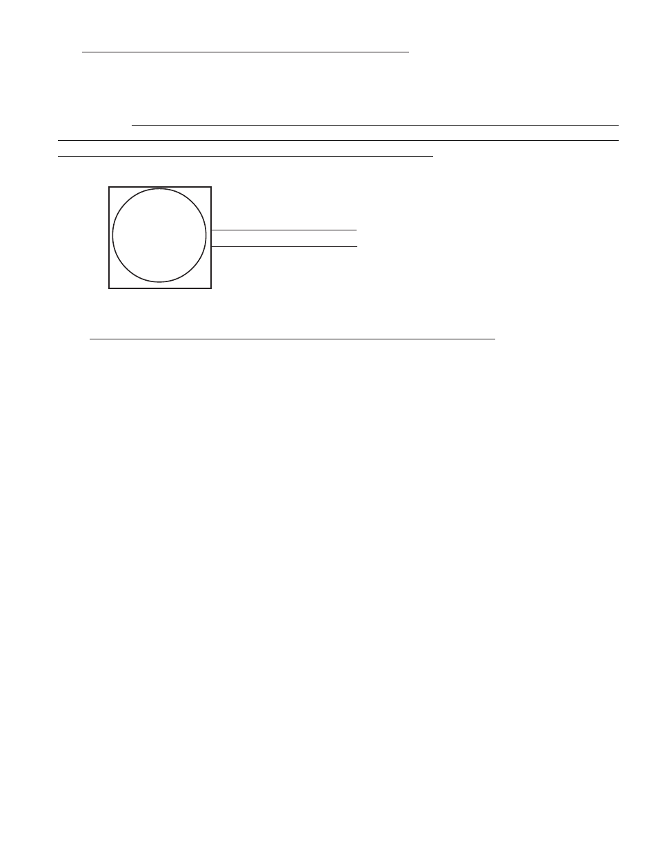
3 6
CGR
Power & Ground
Power (Red, Pin 1)
Gnd (Black, Pin 14)
To Main Bus via 5-amp Breaker.
To Aircraft Ground.
4.10 Connect the CGR Harness to the CO-Guardian CO Detector:
If a CO detector was installed, connect the RS232 output from the Remote Mounted 353-201 (experimental
only) or 452-201-011 (certified) CO Detector to Pin 11 (Port 3 In) on the CGR. Refer to CO-Guardian’s
installation instructions for further information on the CO Detector.