7 install the interface circuit for annunciators – Electronics International CGR-30P User Manual
Page 23
D.
D.
D.
D.
D. Fuel Pressure Transducer Installation:
Fuel Pressure Transducer Installation:
Fuel Pressure Transducer Installation:
Fuel Pressure Transducer Installation:
Fuel Pressure Transducer Installation:
Find a convenient location on the firewall or a bracket
and mount the pressure transducer with the clamp
provided. The fuel pressure line does not have to be
routed into the cabin area although you will need access
on the cabin side of the firewall to tighten the pressure
transducer clamp nut. Do not mount the pressure transducer to an engine baffle
or directly onto the engine with the transducer supported by an adapter or
fitting. Vibration can cause the adapter to break, resulting in loss of engine fuel. The
pressure transducer is equipped with a 1/8" NPT male port. This port can be adapted to
any fuel pressure line. Use only a flexible hose and fittings suitable for aircraft use.
Route a flexible fuel pressure line from the primary fuel pressure pick up point to the
pressure transducer and tighten all fittings. Do not use the case of the pressure
transducer to tighten the pressure fittings. Maintain any restrictive
orifice currently in the system.
* Some fittings you may want to consider using are listed above.
E.
E.
E.
E.
E. Other Pressure Transducer Installations:
Other Pressure Transducer Installations:
Other Pressure Transducer Installations:
Other Pressure Transducer Installations:
Other Pressure Transducer Installations:
Other pressure transducers should be mounted in the aircraft in the same manner as the Gyro Vacuum
Transducer or the Oil and Fuel Pressure Transducers, as appropriate. Note: Any unused + or -
pressure inputs must be wired to a ground pin on the EDC 37-pin connector.
2.7 Install the Interface Circuit for Annunciators:
Any Temperature or Resistive Fuel Level channel on the EDC may be used to monitor the state of a
switch, relay or output from a device. This output can be used to trigger a light (annunciator) on the
CGR. Annunciator lights such as Canopy Latch, Baggage Door, Deice, Pitot Heat, Fire, etc. can be
displayed on the Main or System screen on the CGR.
To monitor a voltage, a VI-221 (Voltage Interface Unit) will be required. This consists of a 221K
ohm resistor heat shrunk between two wires with a D-Sub pin crimped on one end. The following
methods may be used to interface an EDC channel (using a VI-221) to a switch, relay or device:
A.
A.
A.
A.
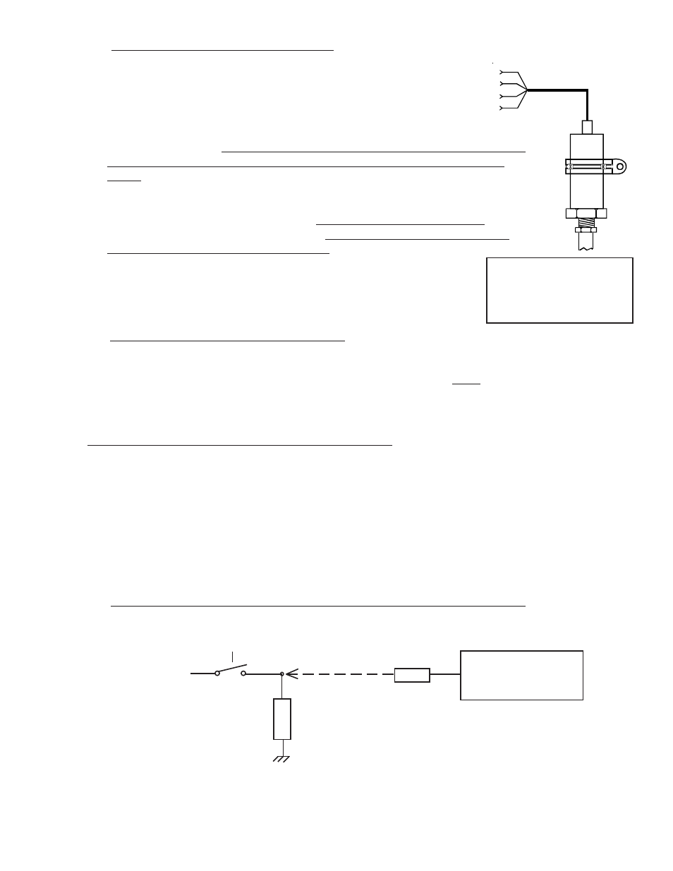
A. Monitoring a Signal That Switches Between Any Voltage and Ground:
Monitoring a Signal That Switches Between Any Voltage and Ground:
Monitoring a Signal That Switches Between Any Voltage and Ground:
Monitoring a Signal That Switches Between Any Voltage and Ground:
Monitoring a Signal That Switches Between Any Voltage and Ground:
1 4
The PT-30GA Pressure
Transducer is used on most
engines for pressures up to
40 psi.
(Red)
(Blk)
(Grn)
(Wht)
To EDC
Press Input
(Top Connector)
EDC
Temp or Resistive Fuel
Level Channel.
Device, Switch or Relay
Bus or any Voltage
Load
VI-221