17 install the edc-33p – Electronics International CGR-30P User Manual
Page 35
2 6
A. Find an appropriate mounting location on the
aircraft instrument panel for the CP-1 Control Pot.
The Pot will require a 2" clearance behind the
aircraft instrument panel.
B. Mark the aircraft instrument panel and drill a 1/4"
hole for the Pot.
C. Mount the Pot from behind the aircraft instrument
panel and install the knob.
2.16 Install the Master Warning (red) and Caution (yellow) Lights:
The Warning and Caution Lights do not have to be installed unless the CGR is
installed more than 8" from the pilot’s visual centerline.
A. Locate the Red (AL-1R) and Yellow (AL-1Y) lights in the kit. Find an
appropriate mounting location within 8" of the pilot's visual centerline.
The lights will require 3/4" clearance behind the aircraft instrument
panel.
B. The CGR-30P remote lights and placard must be installed in a location
where the placard will be readable in all lighting conditions. Installing the annunciators near an
exiting lighting source or installing a post light are acceptable methods of compliance, other methods
may also be acceptable.
C. Mark the aircraft instrument panel and drill a 5/16" hole for each light. Install the Red Warning Light
and the Yellow Caution Light from behind the aircraft instrument panel.
Note: If the CGR Master Warning and Caution Outputs are connected to other lights or devices, the
current must be limited to 0.1 amps. The outputs pull to ground when active.
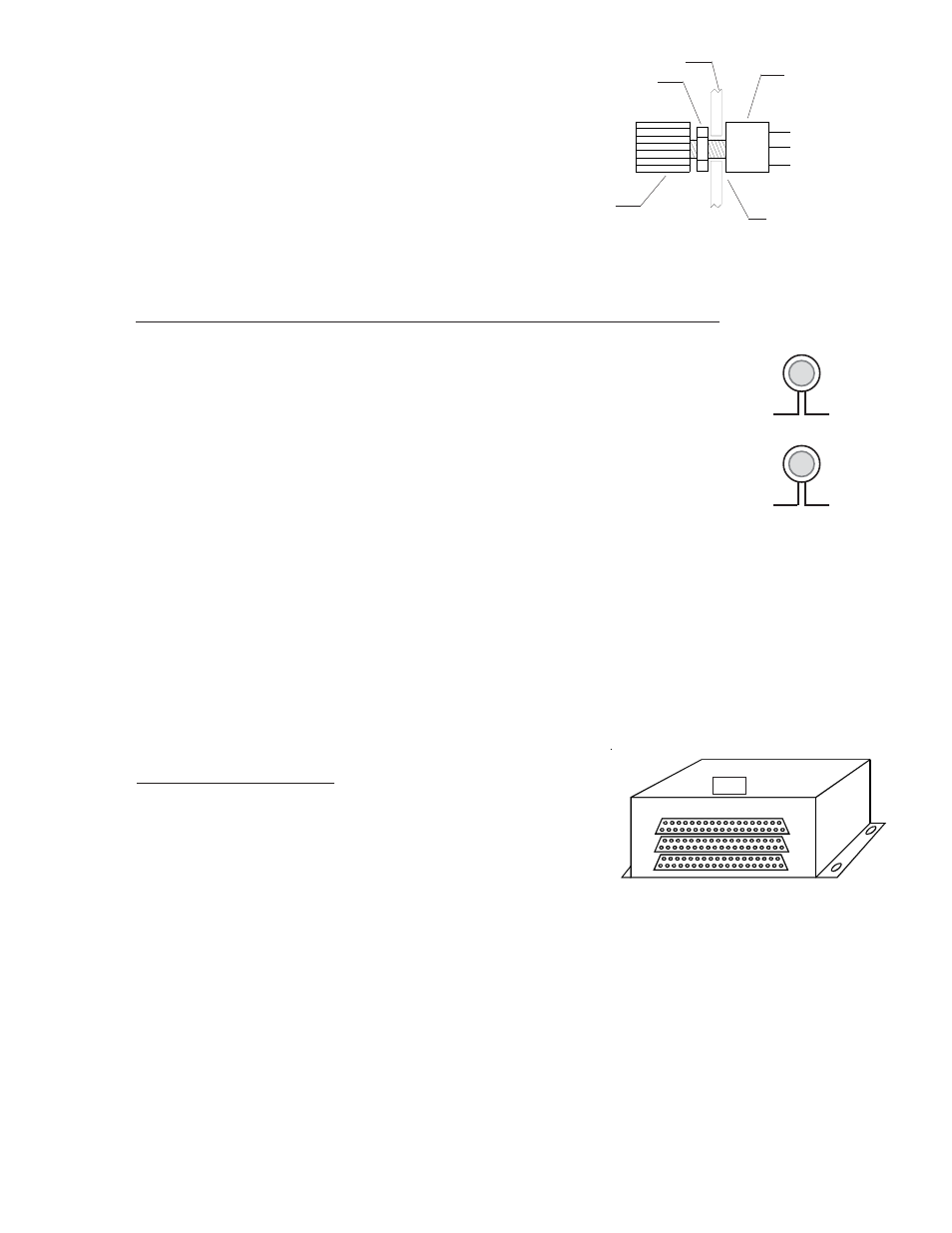
2.17 Install the EDC-33P:
The EDC-33P (Engine Data Converter) converts all of the analog
engine signals into serial data which is output to the CGR display via
one wire (5V Serial). The EDC unit measures 4.5" long by 3.5" wide
by 2.2" high. There are three 37-pin D-sub connectors that interface
to the various probes, modules or direct connections to the aircraft.
Mount the EDC on the inside firewall under the aircraft instrument panel or in an equipment bay. For a twin-
engine aircraft the EDC can be mounted on the opposite side of the firewall of the engine or in the cabin or
equipment bay. Use the holes in the bottom plate of the EDC to mount the unit. Be sure you will have enough
room to connect the three D-sub connector wire harnesses to the EDC. Note: If you run out of channels on the
EDC, a second EDC may be installed and connected to the CGR.
When routing the EDC wire harnesses refer to the Top, Middle and Bottom "EDC Wiring Work Sheets" found
at the back of this manual. Insure no wires obstruct the freedom of travel of any controls.
Nut
Pot
1/4" Hole
Knob
Aircraft Instrument Panel
To CGR
(Wht/Orng)
CP-1
To CGR
To Bus
(Yellow)
To CGR
To Bus
(Red)
Top