Electronics International CGR-30P User Manual
Page 44
3 5
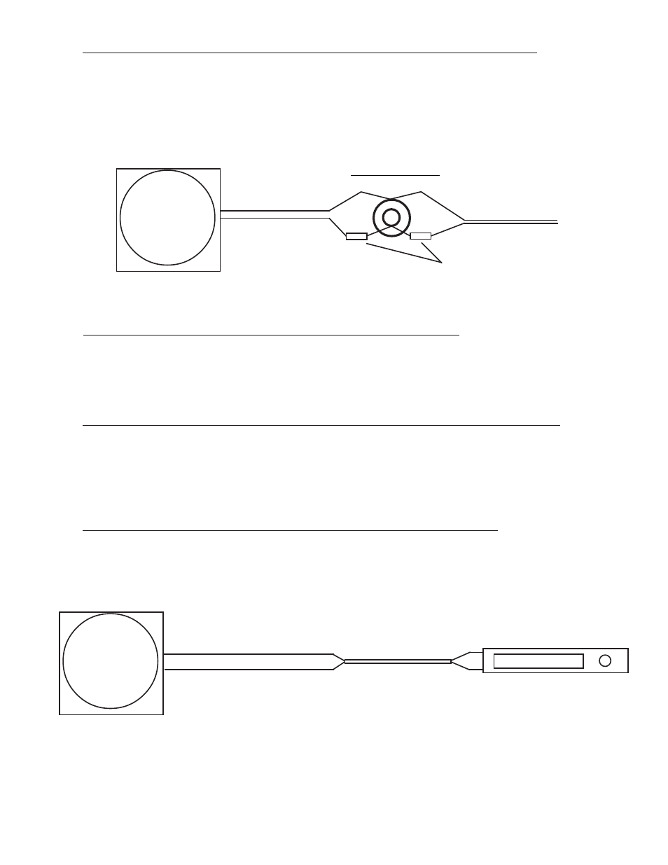
4.5 Connect the CGR Harness to the Audio Panel (OEM/Experimental):
If the voice alarms provided by the CGR are to be used, route the two CGR Voice Warning Out wires to the
Audio Panel, cut the wires to length and connect to the Audio Panel Aux input and ground. If an audio input is
not available on the Audio Panel (or an Audio Panel is not installed) you can connect the CGR Voice Warning
Out wires to the pilot headset jack. With this installation a 49.9 ohm 1/4 watt resistor will need to be installed
in series with the CGR +Voice Warning Out wire and the audio feed wire to the jack.
4.6 Connect the CGR Harness to the Backlight Control Pot:
Route the CGR Back Light Control Input wire (orange) to the aircrafts existing backlight control pot, cut the
wires to length, install the appropriate connector and connect to the pot.
4.7 Connect the CGR Harness to the Moving Map Data Out from the GPS:
If the CGR is to provide fuel data to the current way point, route the CGR "Moving Map Data In" wire (green
wire in a 4 wire cable) to the Moving Map Data Output Port on the GPS. Cut the wire to length, install the
appropriate connector and connect to the GPS port.
4.8 Connect the CGR Harness to the Fuel Data Input on the GPS:
If the GPS is capable of displaying fuel data and this feature is to be used, route the CGR "Fuel Data Out" wire
(white wire in a 4-wire cable) to the Fuel Data Input Port on the GPS. Cut the wire to length, install the appro-
priate connector and connect to the GPS port.
+Voice
(Wht/Blue, Pin 11)
-Voice
(Wht/Gray, Pin 24)
Audio Feed (from Radios)
Pilot's Audio Jack
49.9 Ohms
Gnd
CGR
Voice Output
Moving Map Data In (Grn, Pin 3)
Fuel Flow Data Out (Wht, Pin 15)
Wire Cable
GPS
CGR
GPS Input &
Output