15 install the intensity control pot (optional) – Electronics International CGR-30P User Manual
Page 34
2.13 Install the Resistive Fuel Level Module (RFLM-4-X):
The RFLM-4 is a Resistive Fuel Level Module that provides pull-up resistors for 4
resistive fuel level sensors. This module is required to interface an EDC Resistive
Fuel Level Input to a Resistive Fuel Sensor.
Warring:
Warring:
Warring:
Warring:
Warring: DO NOT connect an RFLM-4 to the output of an existing aircraft’s
Capacitive System, damage to the system may occur. The small output voltage of
an existing capacitive system currently drives a fuel level gauge. This output
wire should be routed to one of the resistive fuel level inputs on the EDC with NO
connection to an RFLM unit.
There are two RFLM-4 modules available. The RFLM-4-12V operates
on a 12-volt electrical system and the RFLM-4-24V operates on a 24-
volt electrical system. The appropriate model must be used.
Mount the RFLM-4-X to the inside firewall or to an equipment bay
under the aircraft instrument panel. Use the holes in the bottom plate
to mount the unit. Only two mounting holes are required.
Note: For each Fuel Level Channel on the EDC you can use either the Resistive Input or the Capacitive Input, but
not both.
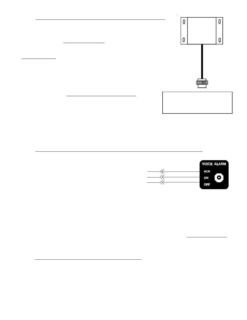
2.14 Install the Voice Alarm Control Panel (OEM or Experimental Only):
If the voice alarms provided by the CGR are to be
used, the AV-17CP Control Panel will need to be
installed in the aircraft instrument panel.
A. Locate the Control Panel and Switch in the
AV-17CP packet. Find an appropriate
mounting location on the aircraft instrument panel for the Control Panel and
Switch. The Switch will require a 3/4" clearance behind the aircraft instru-
ment panel.
B. Using the AV-17CP Control Panel as a template, mark the aircraft instrument panel and drill a 1/4"
hole for the AV-17CP Switch.
C. Mount the Switch from behind the aircraft instrument panel. Be careful not to damage the
silkscreening on the Control Panel. The Switch must be mounted with the white/orange wire up
white/orange wire up
white/orange wire up
white/orange wire up
white/orange wire up.....
The lock washer should be mounted on the Switch and behind the aircraft instrument panel.
2.15 Install the Intensity Control Pot (Optional):
The backlight display intensity of the CGR is controlled by an external source. The CGR will work with any
rheostat and with any voltage swing. The input voltage levels for a bright and dim setting are programmable.
If a rheostat is not currently installed in the aircraft, Electronics International's Intensity Control Pot (CP-1) can
be installed.
2 5
To EDC Resistive Fuel
Level Inputs (Bottom Connector)
and the Fuel Level Sensor.
AV-17CP, Control Panel
White/Brown
White/Red
White/Orange
(OFF)
(ACK)
(+5V)
To CGR