1 attach the cgr 25-pin d-sub connector to the cgr – Electronics International CGR-30P User Manual
Page 43
4.1 Attach the CGR 25-pin D-sub Connector to the CGR:
Secure the connector using the supplied mounting screws.
4.2 Connect the EDC 5V-Serial Output Wire to the CGR 5V-Serial Input Wire:
Route the EDC 5V-Serial output wire to the back of the CGR Display, cut the wires to length and splice them to
the appropriate CGR 5V-Serial input wire.
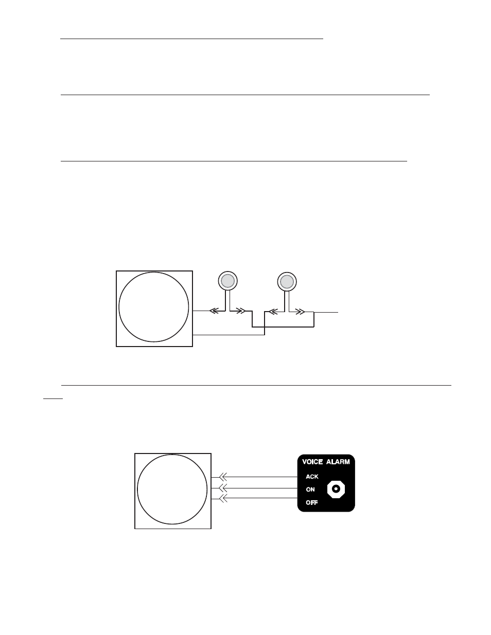
4.3 Connect the CGR Harness to the Master Warning and Caution Lights:
If the Warning and Caution Lights are installed, route the CGR Master Warning Out wire (White/Yellow, Pin
10) to the Master Warning (Red) Light (AL-1R) White/Yellow wire, cut the wires to length, install the appropri-
ate connector and connect to the AL-1R.
Route the CGR Master Caution Out wire (White/Yellow, Pin 23) to the Master Caution (Yellow) Light (AL-1Y)
White/Yellow wire, cut the wires to length, install the appropriate connector and connect to the AL-1Y.
3 4
4.4 Connect the CGR Harness to the Voice Alarm Control Panel (OEM/Experimen-
tal):
If the voice alarms provided by the CGR are to be used, route the three CGR Voice Control wires to the AV-
17CP, cut the wires to length, install the appropriate connectors and connect to the AV-17CP.
Pin 10
To CGR/EDC
5-amp Circuit
Breaker
Wht/Yel
Red
Red
Wht/Yel
Red
Y e l
Pin 23
CGR-30
Control Panel
(AV-17CP)
White/Brown
White/Red
White/Orange
(OFF)
(ACK)
(+3.3V)
CGR
Voice Control
Inputs
25
13
12