Teledyne 2010B - Split architecture thermal conductivity analyzer User Manual
Page 33
Teledyne Analytical Instruments
Thermal Conductivity Analyzer
Part I: Control Unit
Part I 3-11
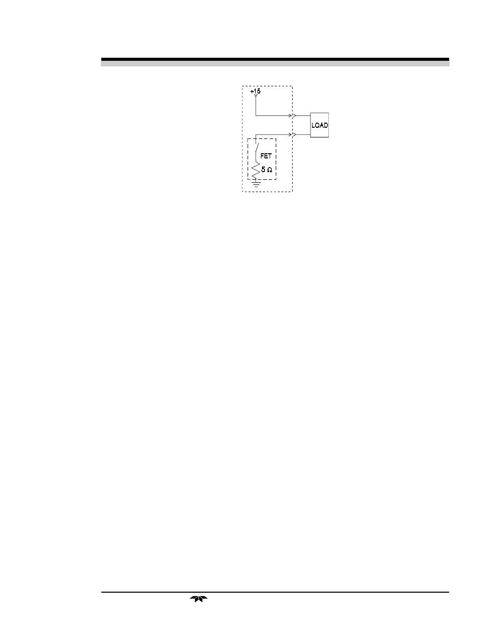
Figure 3-7: FET Series Resistance
3.4
Testing the System
Before plugging the instrument into the power source:
•
Check the integrity and accuracy of the gas connections. Make
sure there are no leaks.
•
Check the integrity and accuracy of the electrical connections.
Make sure there are no exposed conductors
•
Check that the pressure and flow of all gases are within the
recommended levels, and appropriate for your application.
Power up the system, and test it by performing the following
operations:
1. Repeat the Self-Diagnostic Test as described in chapter 4, section
4.3.5.
3.5 Warm Up at Power Up
Every time the unit is turned on, the instrument stays with the introduc-
tion screen for thirty minutes. This is to allow the cell to come up to tem-
perature (50
o
C). The only way to bypass this warm up period is by pressing
any key once, such as the Enter key.
The instrument warms up for half an hour so that it will not receive a
remote calibration signal, send false readings to a monitor system, or, again,
be calibrated by an untrained operator while the cell is cold.
NOTE:There is no feedback on whether the working temperature
has been achieved by cell to the software. If instrument power
is interrupted for only a brief time, the instrument will wait
thirty minutes again. Press the ENTER key to bypass self-
diagnostic mode.