Mounting template for permanent installations – PERKO 0181 User Manual
Page 2
Mounting Option #1
FIGURE NO. 0181 SURFACE MOUNT
L.E.D. UNDERWATER LIGHT
Mounting Options and Installation Instructions
Please Read All Instructions Before Proceeding
For wiring through transom directly behind light.
a. Position the template where the light is to be mounted.
b. Where indicated on the template drill a 5/16” dia. hole for the wire to
pass through the hull.
c. Drill three (3) clearance holes for #8 size mounting screws.
d. Epoxy inside all holes to insure that water will not be absorbed into the
hull in case of water intrusion.
e. After epoxy dries, pass the wire through the hole.
f. Put a generous amount of sealant on the back of the light.
g. Attach the back of the light flush against the mounting surface, using
number 8 R.H. or Pan Head screws. Remove excess sealant.
h. Attach the power cable to a fused, switched power source. Observe
polarity. Red lead is connected to positive. Each light draws less than
1/2 amp at 12 volts.
For wiring through a hole on the mounting surface above
the location of the light, i.e. a hole above the waterline.
a. Follow instructions a, c, d & g as stated above.
b. No sealant is required for the light.
c. Route wire along the mounting surface to desired location, then drill
and seal an appropriate hole to enter the boat and connect to a fused,
switched power source. Observe polarity. Red lead is
connected to positive. Each light draws less than 1/2 amp at 12 volts.
Portable installation with wiring over the transom.
a. Affix a strip of waterproof Velcro
®
type product to the mounting
surface while the boat is out of the water. Be sure the surface is clean
before applying.
b. Attach another strip to the back of the light.
c. Press the two together when desired to temporally mount the light.
d. Pass the cord over the transom. Connect it to a fused power source.
Observe polarity. Red lead is connected to positive. Each light draws
less than 1/2 amp at 12 volts.
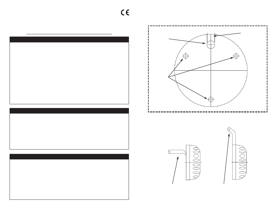
MOUNTING TEMPLATE
FOR PERMANENT INSTALLATIONS
CUT ALONG DOTTED LINES
Configuration of cable
for mounting
option #1
Configuration of cable
for mounting
options #2 & #3
Drill 3
Clearance
Holes for
#8 Screws
Drill 5/16”
Hole for
Wiring
(If Needed)
Cat. Nos.
0181DP1WHT
0181DP2WHT
Cable
Direction
Channel
Mounting Option #2
Mounting Option #3