PERKO 0615 User Manual
Template
Cat. No. 0615 Series
Stealth L.E.D. Bi-Color Lights
Patent Pending
These lights are designed for use on the following:
Stealth I Series:
1nm visibility. For use on power driven vessels
under 12 meters (39.4 ft.) in length operating on a nominal 12 volt system.
Stealth II Series:
2nm visibility. For use on power driven vessels
under 20 meters (65.6 ft.) in length operating on a nominal 12 volt system.
In order to comply with ʻ72 COLREGS and the U.S. Inland Rules, the following must be adhered
to:
MOUNTING INFORMATION
Read all instructions before proceeding
1). For proper light selection, positioning and configuration, refer to the A.B.Y.C. Standard A-16*,
the ʻ72 COLREGS* and the U.S. Inland Rules*.
2). For installations on conductive surfaces (such as aluminum boats), a gasket set (Perko Cat.
No. 0615000GKT) is available to insure isolation of the fixture and minimize stray current
corrosion. Refer to instructions included with the gasket set for additional mounting details.
3). These lights are designed to be mounted on a horizontal surface.
4). Draw a 6 inch long reference line through the center of the selected mounting location and
parallel to the centerline of the boat.
5). Cut out the mounting template. Place it on the mounting surface such that the reference line
(drawn above) is directly underneath the reference line marked on the template.
6). Drill 2 holes through the template to accommodate #8 pan head mounting screws. Drill a 5/16
inch hole (or 7/16 inch hole if gasket set is installed) to accommodate the electric wiring.
7). Attach supply connections to the light, making sure to wire in accordance with both A.B.Y.C.
Standard E-9* and U.S. Coast Guard Safety Standards for Boat Electrical Systems (33 CFR
183)*. Observe polarity.
8). Mount the light in accordance with the template.
9). These lights use L.E.D.ʼs and therefore are not serviceable. Do not attempt to open the lens.
* The above referenced Standards can be obtained from:
1) American Boat & Yacht Council, Inc
2) U.S. Coast Guard
613 Third Street, Suite 10
Washington D.C. 20593
Annapolis, MD 21403
(or your local C.G. office)
PERKO, Inc.
16490 N.W. 13th Avenue
07/12
Miami, Florida 33169-5707
0615INS1
www.perko.com
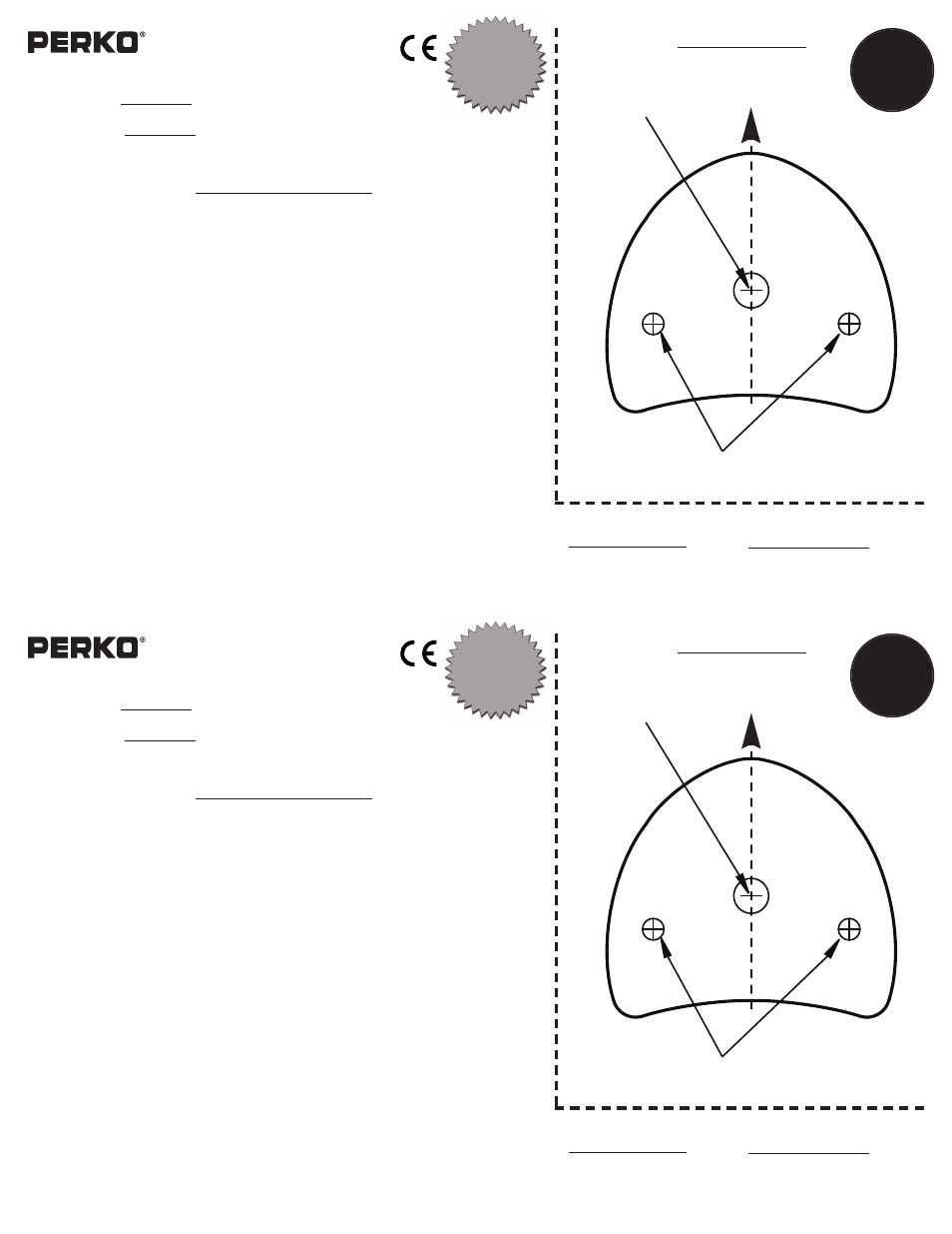
TEMPLATE
AHEAD
RED
GREEN
Drill 5/16” hole
for Electric Wiring
(7/16” hole if gasket set
is installed)
Drill for
#8 Pan Head Screws
Reference Line
This is a
3/4” circle in
order to scale
internet
printed
templates
Stealth I Series: 1nm
0615000STS,
0615DP0STS
0615000BLK, 0615DP0BLK
0615000WHT, 0615DP0WHT
Stealth II Series: 2nm
0615002STS, 0615DP2STS
0615002BLK, 0615DP2BLK
0615002WHT, 0615DP2WHT
Perko Cat. Nos:
USCG
APPROVAL
33 CFR 183.810
Visibility: Varies
Tested By: IMANNA Labs.
Date: 4/22/08, 4/16/12
Meets ABYC A-16
Cat. No. 0615 Series
Stealth L.E.D. Bi-Color Lights
Patent Pending
These lights are designed for use on the following:
Stealth I Series:
1nm visibility. For use on power driven vessels
under 12 meters (39.4 ft.) in length operating on a nominal 12 volt system.
Stealth II Series:
2nm visibility. For use on power driven vessels
under 20 meters (65.6 ft.) in length operating on a nominal 12 volt system.
In order to comply with ʻ72 COLREGS and the U.S. Inland Rules, the following must be adhered
to:
MOUNTING INFORMATION
Read all instructions before proceeding
1). For proper light selection, positioning and configuration, refer to the A.B.Y.C. Standard A-16*,
the ʻ72 COLREGS* and the U.S. Inland Rules*.
2). For installations on conductive surfaces (such as aluminum boats), a gasket set (Perko Cat.
No. 0615000GKT) is available to insure isolation of the fixture and minimize stray current
corrosion. Refer to instructions included with the gasket set for additional mounting details.
3). These lights are designed to be mounted on a horizontal surface.
4). Draw a 6 inch long reference line through the center of the selected mounting location and
parallel to the centerline of the boat.
5). Cut out the mounting template. Place it on the mounting surface such that the reference line
(drawn above) is directly underneath the reference line marked on the template.
6). Drill 2 holes through the template to accommodate #8 pan head mounting screws. Drill a 5/16
inch hole (or 7/16 inch hole if gasket set is installed) to accommodate the electric wiring.
7). Attach supply connections to the light, making sure to wire in accordance with both A.B.Y.C.
Standard E-9* and U.S. Coast Guard Safety Standards for Boat Electrical Systems (33 CFR
183)*. Observe polarity.
8). Mount the light in accordance with the template.
9). These lights use L.E.D.ʼs and therefore are not serviceable. Do not attempt to open the lens.
* The above referenced Standards can be obtained from:
1) American Boat & Yacht Council, Inc
2) U.S. Coast Guard
613 Third Street, Suite 10
Washington D.C. 20593
Annapolis, MD 21403
(or your local C.G. office)
PERKO, Inc.
16490 N.W. 13th Avenue
07/12
Miami, Florida 33169-5707
0615INS1
www.perko.com
TEMPLATE
AHEAD
RED
GREEN
Drill 5/16” hole
for Electric Wiring
(7/16” hole if gasket
set is installed)
Drill for
#8 Pan Head Screws
Reference Line
This is a
3/4” circle in
order to scale
internet
printed
templates
Stealth I Series: 1nm
0615000STS,
0615DP0STS
0615000BLK, 0615DP0BLK
0615000WHT, 0615DP0WHT
Stealth II Series: 2nm
0615002STS, 0615DP2STS
0615002BLK, 0615DP2BLK
0615002WHT, 0615DP2WHT
Perko Cat. Nos:
USCG
APPROVAL
33 CFR 183.810
Visibility: Varies
Tested By: IMANNA Labs.
Date: 4/22/08, 4/16/12
Meets ABYC A-16