PERKO 0955 User Manual
PERKO Lighting
Cat No. 0955 Series Sidelights
The above lights are designed for use on sail or power driven vessels under
12 Meters (39.4 ft.) in length operating on nominal 12 volt or 24 volt systems.
In order to comply with ‘72 COLREGS and the U.S. Inland Rules, the following
must be adhered to:
MOUNTING INSTRUCTIONS
Read all instructions before proceeding
1). These instructions show the orientation of each light after the proper mounting location has been
determined. For proper light selection, positioning and configuration, refer to A.B.Y.C. Standard A-
16*, the ‘72 COLREGS* and the U.S. Inland Navigation Rules*. These lights are supplied complete
with 12 volt bulbs (Cat. No. 0071DP0CLR 12V, 10W), however, 24 volt bulbs (Cat No.
0072DP1CLR) are available for 24 volt systems. Note: PERKO Series 0955 side lights used with
a 24V Bulb (Cat. No. 0072DP1CLR) are not certified in accordance with 33 CFR 183.810 as these
lights are intended for replacement use only on appropriate vessels constructed prior to 11/1/03. All
previous certifications apply.
2). These lights are designed to be mounted on a vertical surface that is parallel to the centerline of the
boat.
3). Draw a 6 inch long horizontal reference line through the center of the selected mounting location
and parallel to the centerline of the boat.
4). Cut out the mounting template on the opposite side. Tape it on the mounting surface such that the
reference line (drawn above) is directly underneath the reference line marked on the template, and
the arrow on the template points ahead (not astern).
5). Drill 3 holes through the template for #4 mounting screws.
6). Drill a 1/2 inch diameter hole as indicated to provide the necessary clearance for the supply con-
nections.
7). Attach supply connections to the light, making sure to wire in accordance with both A.B.Y.C.
Standard E-9 and U.S. Coast Guard Safety Standards for Boat Electrical Systems (33 CFR 183)*.
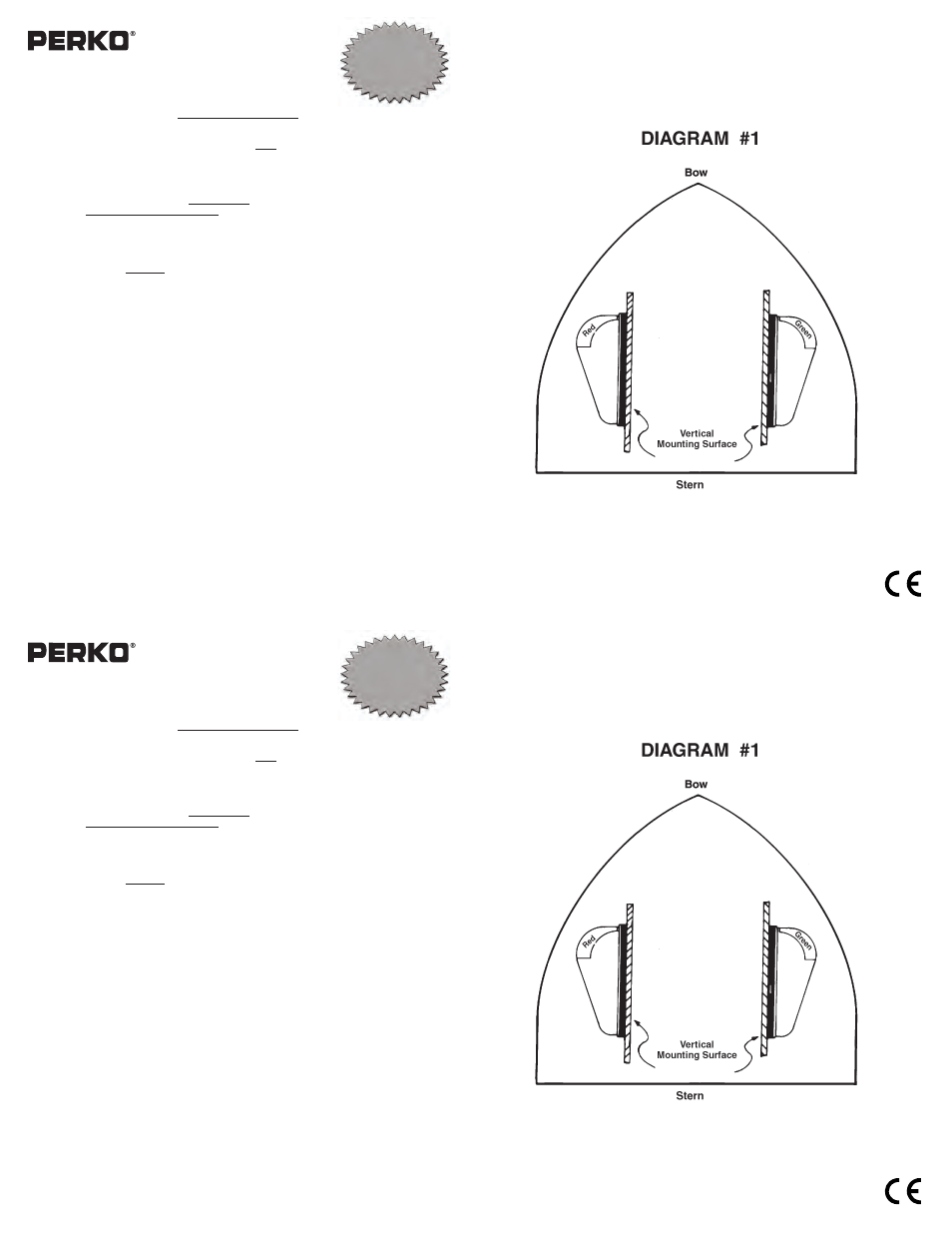
8). Mount the light on the correct side of the boat in accordance with Diagram #1. Use the mounting
screws to pull the top down to the base until it snaps in place. Note that there are thin reference
marks around the outside of the black base that must be aligned with the reference line (drawn in
Step #3) for the final accuracy of the mounting orientation.
9). Recheck that red shows to port and green shows to starboard.
* The above referenced standards can be obtained from:
1).
American Boat & Yacht Council, Inc.
2). U.S. Coast Guard
613 Third Street, Suite 10
Washington, D.C. 20593
Annapolis, MD 21403
(or your local C.G. Office)
11/06
PERKO, Inc.
0955INS1
16490 N.W. 13th Avenue
Miami, FL 33169-5707
www.perko.com
USCG APPROVAL
33 CFR 183.810
Visibility: 1nm
Tested By: IMANNA Labs.
Date: 2/4/03
Meets ABYC A-16
Cat No. 955 Series Sidelights
The above lights are designed for use on sail or power driven vessels under
12 Meters (39.4 ft.) in length operating on nominal 12 volt or 24 volt systems.
In order to comply with ‘72 COLREGS and the U.S. Inland Rules, the following
must be adhered to:
MOUNTING INSTRUCTIONS
Read all instructions before proceeding
1). These instructions show the orientation of each light after the proper mounting location has been
determined. For proper light selection, positioning and configuration, refer to A.B.Y.C. Standard A-
16*, the ‘72 COLREGS* and the U.S. Inland Navigation Rules*. These lights are supplied complete
with 12 volt bulbs (Cat. No. 0071DP0CLR 12V, 10W), however, 24 volt bulbs (Cat No. 0072DP1
CLR) are available for 24 volt systems. Note: PERKO Series 0955 side lights used with
a 24V Bulb (Cat. No. 0072DP1CLR) are not certified in accordance with 33 CFR 183.810 as these
lights are intended for replacement use only on appropriate vessels constructed prior to 11/1/03. All
previous certifications apply.
2). These lights are designed to be mounted on a vertical surface that is parallel to the centerline of the
boat.
3). Draw a 6 inch long horizontal reference line through the center of the selected mounting location
and parallel to the centerline of the boat.
4). Cut out the mounting template on the opposite side. Tape it on the mounting surface such that the
reference line (drawn above) is directly underneath the reference line marked on the template, and
the arrow on the template points ahead (not astern).
5). Drill 3 holes through the template for #4 mounting screws.
6). Drill a 1/2 inch diameter hole as indicated to provide the necessary clearance for the supply con-
nections.
7). Attach supply connections to the light, making sure to wire in accordance with both A.B.Y.C.
Standard E-9 and U.S. Coast Guard Safety Standards for Boat Electrical Systems (33 CFR 183)*.
8). Mount the light on the correct side of the boat in accordance with Diagram #1. Use the mounting
screws to pull the top down to the base until it snaps in place. Note that there are thin reference
marks around the outside of the black base that must be aligned with the reference line (drawn in
Step #3) for the final accuracy of the mounting orientation.
9). Recheck that red shows to port and green shows to starboard.
* The above referenced standards can be obtained from:
1).
American Boat & Yacht Council, Inc.
2). U.S. Coast Guard
613 Third Street, Suite 10
Washington, D.C. 20593
Annapolis, MD 21403
(or your local C.G. Office)
11/06
PERKO, Inc.
0955INS1
16490 N.W. 13th Avenue
Miami, FL 33169-5707
www.perko.com
USCG APPROVAL
33 CFR 183.810
Visibility: 1nm
Tested By: IMANNA Labs.
Date: 2/4/03
Meets ABYC A-16