PERKO 0178 User Manual
Page 2
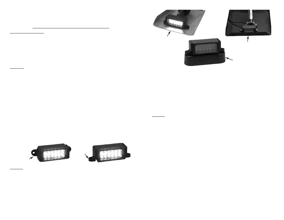
FIG. NO. 0178 TRIM TAB
SURFACE MOUNT
L.E.D. UNDERWATER LIGHT
Please Read All Instructions Before Proceeding
MOUNTING OPTIONS:
1. Surface Mount with wiring directly through transom behind light.
2. Horizontal Mount on trim tab.
3. Vertical Mount on trim tab.
Caution:
Although fully waterproof, these lights are not designed to withstand the
force of moving water if mounted on the underneath of the trim tab (or
similarly exposed surface on the hull). It can be mounted on the transom.
Option 1
FOR VERTICAL SURFACE MOUNTING ON TRANSOM WITH WIRING
DIRECTLY BEHIND THE LIGHT.
a. Position the light where it is to be mounted.
b.
Mark a hole location for the cable to pass directly through the transom. Drill
a 5/16” dia. hole for the cable to pass through the hull directly behind the
light. Pass the cable through the hull and position the light on the transom.
Mark bracket hole locations, remove light and cable.
c.
Drill two (2) holes for mounting brackets to accommodate #8 pan head
screws.
d.
Epoxy inside all holes to insure that water will not be absorbed into the hull
in case of water intrusion.
e.
After epoxy dries, pass the cable through the transom hole.
f.
Put a generous amount of sealant on the back of the light.
g.
Position the mounting brackets on the light for vertical mounting, as shown
in Diagram #1.
h.
Attach the back of the light flush against the mounting surface, using #8 P.H.
screws (not included). Remove excess sealant.
i.
Attach the power cable to a fused, switched power source. Observe
polarity. Black lead is negative, white lead is positive. Each light draws less
than 1/2 amp at 12 volts.
Option 2
FOR HORIZONTAL MOUNTING ON TRIM TAB.
a. Attach the mounting brackets so that when the light is mounted the beam
will point aft. (See Diagram #2 for bracket configuration).
b. Choose a mounting location on the trailing edge of the trim tab surface.
Position the the light where it is to be mounted.
Note: Some trim tabs have a flat trailing edge. Others have a folded-up lip.
In the case of the folded lip, a plastic mounting riser is included to elevate
the light above the height of the lip (See Diagram 3).
c.
Mark where the holes are to be drilled for the mounting brackets. Drill an
8/32” diameter hole for each mounting bracket. Bolt the light to the trim tabs
using #8 stainless steel pan head screws (not included).
Diagram #1
Bracket
Configuration
For Vertical
Mounting
Diagram #2
Bracket
Configuration
For Horizontal
Mounting
d.
Route cable along the trim tab mounting surface to the desired entry
location above the waterline. You may choose to use an existing entry
location or drill an 5/16” diameter hole for the cable to enter the boat and
connect to a fused, switched power source. If drilling another hole make
sure to epoxy the inside of the hole to insure that water will not be absorbed
in to the hull in the case of water intrusion.
e.
Use “P” clamps to secure the cable at various locations. Make sure to allow
extra cable slack for travel of the trim tab up and down.
f.
Attach the power cable to a fused, switched power source. Observe
polarity. Black lead is negative, white lead is positive. Each light draws less
than 1/2 amp at 12 volts.
Option 3
FOR VERTICAL MOUNTING ON TRIM TAB.
Some trim tabs have a plate welded vertically to the tab (not shown). The trim
tab actuator is mounted to the forward side of the plate, so the trim tab light can
be mounted to the aft side of the plate.
a. Attach the mounting brackets so that when the light is mounted the beam
will point aft. (See Diagram #1 for bracket configuration).
b. Select a mounting location and position the light vertically on the plate.
c.
Mark where the holes are to be drilled for the mounting brackets and the
cable. Drill a 5/16” dia. hole for the cable to pass through the plate. Drill two
(2) holes for mounting brackets to accommodate #8 P.H. screws. Bolt the
light to the trim tabs using #8 stainless steel P.H. screws (not included).
d.
Route cable along the trim tab mounting surface to the desired entry
location above the waterline. You may choose to use an existing entry
location or drill an 5/16” diameter hole for the cable to enter the boat and
connect to a fused, switched power source. If drilling another hole make
sure to epoxy the inside of the hole to insure that water will not be absorbed
in to the hull in the case of water intrusion.
e.
Use “P” clamps to secure the cable at various locations along the cable
path. Make sure to allow extra cable slack for travel of the trim tab up and
down.
f.
Attach the power cable to a fused, switched power source. Observe
polarity. Black lead is negative, white lead is positive. Each light draws less
than 1/2 amp at 12 volts.
Important: If you do not want the cable to exit directly behind the body
of the light, you will find “knockouts” on either side and on the bottom
of the light that the cable can exit in any of three directions.
Flat Trailing Edge
(Option 2 without
mounting riser)
Trailing Edge with Folded-Up Lip
(Option 2 with mounting riser)
Diagram #3
Light shown with
mounting riser