PERKO 1642 User Manual
PERKO Lighting
Cat. Nos. 1636, 1639 & 1642 Series
Fold Down L.E.D Reduced Glare White All-Round Lights
Patent Pending
The above lights are designed for use on power driven vessels under
20 meters (65.6 ft.) in length operating on a nominal 12 volt system.
In order to comply with ʻ72 COLREGS and the U.S. Inland Rules, the following must be
adhered to:
MOUNTING INFORMATION
Read all instructions before proceeding.
1). For proper light selection, positioning and configuration, refer to A.B.Y.C. Standard A-16
(1), the ʻ72 COLREGS, and the U.S. Inland Rules (2).
2). These lights are designed to be mounted on a horizontal, vertical or angled
surface.
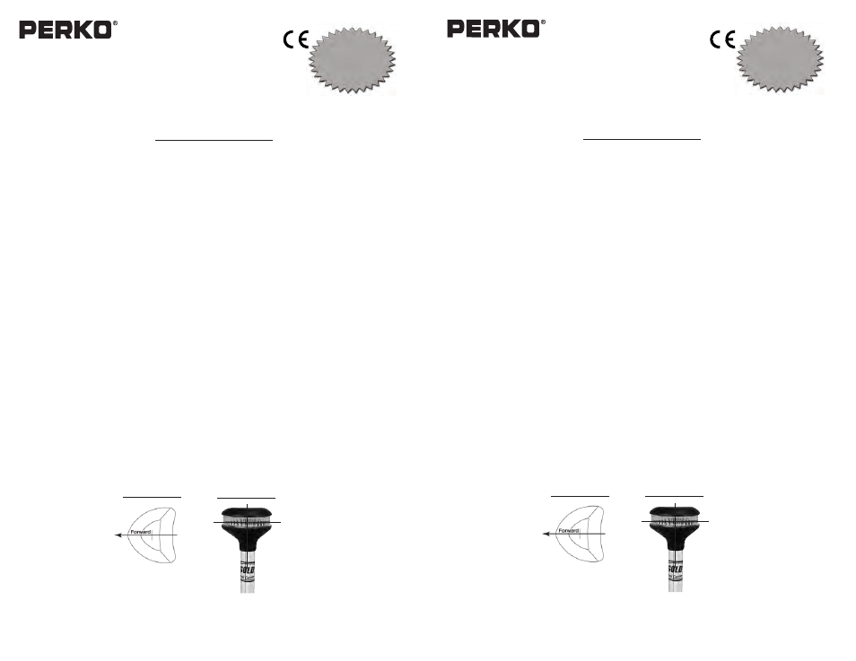
3). Horizontal rotation of these lights is unimportant, as all-round lights have 360° horizontal
arc of visibility. However, aesthetically, mount the light as shown in Diagram #1.
4). Using the base or the plastic mounting insulator as a template, place it on the mounting
surface such that the globe can be adjusted to a vertical position when mounted.
5). Drill mounting holes for #8 screws (not supplied). Use #8 oval or flat head screws on lights
with metal swivel bases and use #8 round or pan head screws on lights with plastic swiv-
el bases.
6). Attach supply connections to the light, making sure to wire in accordance with both
A.B.Y.C. Standard E-9* and U.S. Coast Guard Safety Standards for Boat Electrical
Systems (33 CFR 183)*. Observe polarity.
7). Mount the light. On metal swivel base lights, the plastic mounting insulator
(supplied) and stainless steel screws (not supplied) may be used between the base and
mounting surface to reduce the possibility of electrolysis on dissimilar metals.
8). Adjust pole such that the light is in a vertical position during operation, in order to assure
compliance with the technical details of the regulations and employ the “Reduced Glare”
feature on the 1636/1639/1642 Series optical system. See Diagram #2.
9).
These lights use white L.E.D.ʼs and therefore are not serviceable. The lens/globe is per-
manently sealed and cannot be opened.
*The above referenced standards can be obtained from:
(1) American Boat & Yacht Council, Inc.
(2)
U.S. Coast Guard
613 Third Street, Suite 10
Washington, D.C. 20593
Annapolis, MD 21403
(or your local C.G. Office)
PERKO, INC.
16490 N.W. 13th Avenue
1636INS1
Miami, FL 33169-5707
02/08
www.perko.com
USCG APPROVAL
33 CFR 183.810
Visibility: 2nm
Tested By: IMANNA Labs.
Date: 02/28/12
Meets ABYC A-16
DIAGRAM #1
DIAGRAM #2
Cat. Nos. 1636, 1639 & 1642 Series
Fold Down L.E.D Reduced Glare White All-Round Lights
Patent Pending
The above lights are designed for use on power driven vessels under
20 meters (65.6 ft.) in length operating on a nominal 12 volt system.
In order to comply with ʻ72 COLREGS and the U.S. Inland Rules, the following must be
adhered to:
MOUNTING INFORMATION
Read all instructions before proceeding.
1). For proper light selection, positioning and configuration, refer to A.B.Y.C. Standard A-16
(1), the ʻ72 COLREGS, and the U.S. Inland Rules (2).
2). These lights are designed to be mounted on a horizontal, vertical or angled
surface.
3). Horizontal rotation of these lights is unimportant, as all-round lights have 360° horizontal
arc of visibility. However, aesthetically, mount the light as shown in Diagram #1.
4). Using the base or the plastic mounting insulator as a template, place it on the mounting
surface such that the globe can be adjusted to a vertical position when mounted.
5). Drill mounting holes for #8 screws (not supplied). Use #8 oval or flat head screws on lights
with metal swivel bases and use #8 round or pan head screws on lights with plastic swiv-
el bases.
6). Attach supply connections to the light, making sure to wire in accordance with both
A.B.Y.C. Standard E-9* and U.S. Coast Guard Safety Standards for Boat Electrical
Systems (33 CFR 183)*. Observe polarity.
7). Mount the light. On metal swivel base lights, the plastic mounting insulator
(supplied) and stainless steel screws (not supplied) may be used between the base and
mounting surface to reduce the possibility of electrolysis on dissimilar metals.
8). Adjust pole such that the light is in a vertical position during operation, in order to assure
compliance with the technical details of the regulations and employ the “Reduced Glare”
feature on the 1636/1639/1642 Series optical system. See Diagram #2.
9).
These lights use white L.E.D.ʼs and therefore are not serviceable. The lens/globe is per-
manently sealed and cannot be opened.
*The above referenced standards can be obtained from:
(1) American Boat & Yacht Council, Inc.
(2)
U.S. Coast Guard
613 Third Street, Suite 10
Washington, D.C. 20593
Annapolis, MD 21403
(or your local C.G. Office)
PERKO, INC.
16490 N.W. 13th Avenue
1636INS1
Miami, FL 33169-5707
02/08
www.perko.com
USCG APPROVAL
33 CFR 183.810
Visibility: 2nm
Tested By: IMANNA Labs.
Date: 02/28/12
Meets ABYC A-16
DIAGRAM #1
DIAGRAM #2